www.brian-lambert.co.uk

Former Layouts
Here are details of my original layout and the plans to build another portable layout....My basic requirement was that the layout must be portable and of exhibition quality. It must be able to run standard “00” gauge (4mm) rolling stock and be of British outline. My modelling region is LNER in BR days, in a time span between 1950 and 1960. Mainly steam loco's, but with a smattering of diesel too. Having drawn a plan to scale on my PC, I started to make the baseboards.
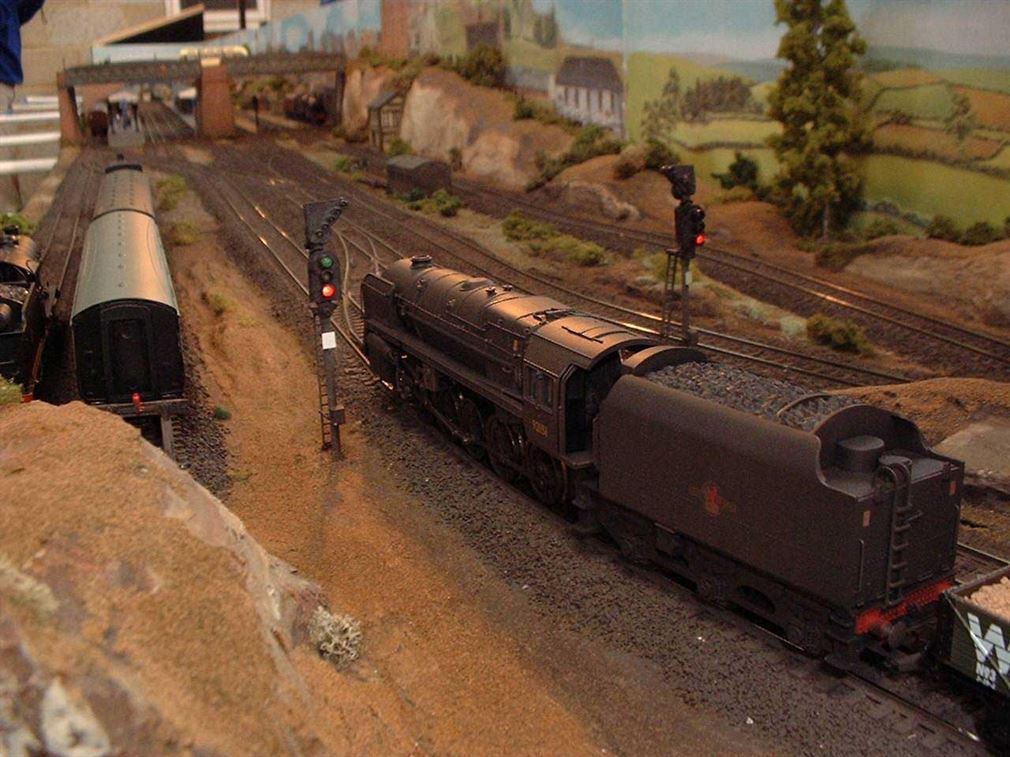
"Ridgley Vale" a "OO" gauge exhibition circuit layout. Measuring some 28' x 8' feet in size, it was certainly no layout for easy home use! Ridgley came into being around 1996 when just three front boards were produced as a simple end to end layout. The following years slowly saw the layout altered and extended into a full circuit and become some 28 feet overall in length. The final layout required a minimum of two operators - Front for control of both up and down lines and the rear for the storage or fiddle sidings. However, it was best operated by three people. Again one person solely for the rear storage sidings but the front of the layout divided up into separate controls of the up and down lines.
The layout was built on a sturdy timber framing and topped by 1/2inch chipboard which made each section fairly heavy to manhandle, but not impossible. Each section was made to approx. 4 x 2 feet (1200 x 600mm) size, though some boards differed in both width and length slightly to enable certain scenic areas to be created. Each board abutting the next and being aligned by metal dowels. The boards were connected together by the use of M6 coach bolts, washers and wing nuts (two per join) and tightened by hand or spanner as required. The whole layout standing on trestles at around 39 inches to the top of baseboard. Electrical connections board to board are made by multi pin plugs and mating sockets.
One front area control panel allows the front of layout operator(s) to switch in track sections, change signal aspects and control the powered turntable. Hand held AMR controllers are connected to the control panel via DIN plugs and chassis sockets. The rear storage/ fiddle sidings having their own home made up and down line controllers and a mimic point control panel all at one end of the sidings. All point operation both front and rear is via the stud and probe method with one CDU for the whole front and a separate home made CDU for the rear sidings point motors. All the track work is Peco Streamline code 100 and live frog points are used wherever possible. Peco PL10 motors with PL13 switches fitted powered the points and the switches providing the frog polarity switching on the front boards and one the rear siding boards the switches provided panel indication to the rear operates mimic panel for the far end from the operators position as these points were to far away to be seen which position they were set too.
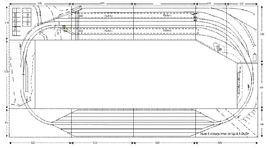
Then track plan is reproduced below.
In the above track feeding plan, it can be seen that there are five 'special feeds' (two on the left and three on the right). These allowed the rear operator to bring a train ready for dispatch around towards the scenic area and hold them but not actually allow them into 'Public view'. Then when ready, the front panel operator would press an "Accept" button on the mimic panel and take the train from this holding section under control of their own speed controller. Similarly the tracks leading towards the storage sidings could hold a train driven in by the front operators controller and out of view until the rear siding operator was ready to drive the train forward into the appropriate siding.
In 2003/4 the whole layout (except rolling stock) was handed over to the Ashford Model Railway Club for their use. I believe it has since been dismantled.
'Betterford' was designed and partly constructed, again for totally portable use and the exhibition circuit.
While this layout below no longer exists, its construction techniques, hints, tips and accompanying photographs may be of great use to anyone starting to build a layout - Portable or permanent.
I tried for the very first time and used virtually all 9mm MDF (Medium Density Fibre board) for the baseboards construction. Even the tops are of MDF! I purchased many 607 x 1220mm (2' x 4') sheets of 9mm (3/8") thick MDF and cut some sheets length ways and others across the narrower side, all into 100mm (4") widths. I ended up with lots of “Planks of MDF” all either 607 or 1220mm long. These were used to make the sides and internal bracing sections. At the same time I purchased sufficient quantity of the 9mm MDF sheet to be used for the layout tops.
A quick word of caution is needed here. MDF by its nature is not a friendly board when being cut, its dust is extremely harmful if inhaled. Always cut the boards outdoors and wear a suitable face mask to cover your nose and mouth. Ensure all dust is removed from the surface of boards before bringing them back indoors. Also remember that MDF is manufactured from compressed paper. It quickly absorbs moisture and swells and becomes pretty useless! It needs an all over coating of some form of sealant. I used quick drying varnish sprayed on from an electric spray gun.
Each top board's sheet was placed upside down and the frame work assembled onto this to match its physical size. I cut half housing joints in the cross members where they intersected each other. Where these met the outer frames I used some 95mm (3 3/4") long off cuts of 44 x 21mm (2” x 1” equivalent) PSE as corner strengtheners. All joints were PVA woodworking adhesive glued and screwed together. I like using 25mm or 40mm x 4 'fast cut' chipboard screws as they are easily driven in. Once the framework was completed, the top was then glued and panel pinned into place. Any minor overlapping of the top to the sides was planed smooth once everything was dry.
Next the legs were constructed from more 44 x 21mm timber, with a cross brace of suitable width glued and screwed at 300mm above floor level. One pair of legs per board is the normal method, except for two boards which are erected diagonally opposite to each other and have two sets of legs each. This allows the layout to be erected from each of these self supporting boards outwards. A piece of 44 x 21mm timber is cut to act as a locking stay which holds the legs into their upright position and gives stability to the boards. As the layout is portable the legs are hinged at the baseboard end by using 30mm (1 1/4”) back flap hinges. Additionally, the locking stay is fixed into position by further back flap hinges, but this time their pivot pin is removed and a 60mm (3”) wire nail is used as a locating pin once the stay is fitted into place. To lock the lower end of the stay to the legs cross brace I devised a 'U' shaped plastic channel which is the width of the cross brace (20mm) and these are pushed over the cross brace and then locked into position with small latches. More recently I have started to use the back flap hinges minus their pivot pins at both ends – only because it’s simpler to make them initially!
So, I have ended up with some eleven MDF baseboards, not all are the same size, with each one matching the next in width and height and overall making up the 4600 x 2300mm (15 x 7'6") layout size.
To ensure perfect track alignment across each board joint, each board's end has two brass dowels fitted. These comprise of a machined mating pair of male and female halves. To fit these the boards are clamped together and the two top surfaces are checked for level across the joint. Once everything is correct, two 7mm holes are drilled through the two abutting side edges about 75mm in from each side edge and as midway down the face as possible. An off cut of the PSE timber is then glued and screwed directly over the inside face where the two holes are on each board. The dowels are then coated with PVA glue and driven into the pre drilled holes.
I have adopted on this layout, reasonably sized latches to hold the sections of boards together. One pair per board joint. These make putting up and dismantling the layout very quick and simple and there's nothing to get lost! Unlike the more conventional M6 Coach bolts, washers and Wing nuts. The latches proved a very tight pull up tension between the two boards, as I've set the hook portion some 1-2 mm further back than normal and when the latches loop engages the hook pressing home the lever of the main latch creates large tensional forces on the loop/hook and this really pulls the boards together. They is no need for any further nut and bolt fixings! The dowels aligning everything as the layout come together. See the photos below.
I now have lots of nice new boards. The next thing was finding them a suitable home, so that all the other items that need doing could be undertaken. I’m perhaps a bit lucky here, as I was able to use one half of a double garage and erect the boards on a semi-permanent basis, while they are completed and even use the area for operating the layout too!
Before anything could be started though I had to install additional lighting and a double power socket, but this was easily undertaken. The floor area was covered with a large tarpaulin obtained at a local market; this keeps the concrete floor’s dust down. I still have to prevent dust and the cold winters draft from coming in via the metal up and over garage door, but I think a similar but smaller tarpaulin with some form of cord operation (Like a window bind) could be used?
Finally, all the boards were erected and track marking out and then track laying could commence. Wherever a point was needed I marked through its Tie Bar central hole with a small nail and then located that mark on the baseboard and drilled a 9mm hole. This allows the Peco electric point motors pin to engage with the tie bar from underneath. I’ve found a 9mm hole gives adequate clearance to allow full normal to reverse operation, so long as the point switch blade is held mid way between the two sides when the hole’s location is firstly marked. The hole doesn’t show that much once ballasting is completed. In addition I glued and screwed some strips of 9mm plywood mounting fillets to the undersides of the baseboard where the point hole appeared and then drill through these with the 9mm drill bit. This ply fillet allows the point motor retaining screws to be easily fitted. See the picture below.
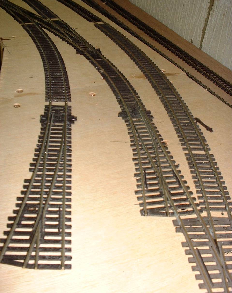
All track is Peco code 100. I would have liked to have used code 75 fine scale, but I don’t think some of my rolling stock would be very happy running on this? So, code 100 wooden sleepers and as large as possible electro frog point turnouts have been used throughout. I planned not to have any curve of less than 600mm (24”) radius, though there are a couple of small radius points were planned to be used in sidings where space was at a premium. The track plan shown above was drawn up, altered umpteen times and then settled upon.
Track was laid directly onto the MDF baseboard tops. I have in the past used an underlay of cork to help deaden the noise, but once the track is ballasted with real stone and then glued the whole mass becomes solid again and seems to defeat the object of the original exercise!
The track was pinned into position with the aid of the very fine Peco track pins, which once the track is ballasted and glued are all removed. The MDF top does mean a fine pilot hole has to be drilled at every pins location, but isn’t to hard to undertake and I use an Archimedean drill with a fine drill bit – about 0.5mm. You will break many drill bits unfortunately, but as the Peco sleepers are fairly soft so even a broken drill bit will pass through and into the tops MDF. Insulated rail joiners are installed as the track laying progresses. Using electro frog points offers much better slow running, but does involve a lot more thought on electrical track feeds and increases the number of insulated rail joint ten fold, but this has to be the price to allow slow speed smooth running.
Unfortunately, due to a move of home the layout was eventually scraped. All the track work was carefully taken up and reused but the MDF boards were all destroyed!
All items appearing on this or any page of this web site are the intellectual property and © copyright of Brian Lambert. Unless otherwise stated.
You MUST NOT make available by placing them in any public domain area or in printed format any copies of Text, Image, Drawing or Video shown on this web site.
No item as listed above should be used, copied, linked to or forwarded by any third party without firstly obtaining the written permission of the web site owner - Brian Lambert.
You may freely and for personal use only, copy or print any areas.
You may refer to this web sites page electronic address detail (URL) in any other media - printed or electronic. Any such referenced URL should commence.... https://www.brian-lambert.co.uk/
Brian Lambert accepts no responsibility for any item appearing on this or any other page of this web site.
All items are given in good faith.