www.brian-lambert.co.uk


Points - Part 1
Points....Firstly some terminology and basic types ..


Insulated frog points, sometimes they are called 'Dead frog or 'Insulfrog'', have as their main advantage the fact that they need no additional work other than fitting them into their correct place on the layout (excluding any form of motorised point operation). All current Hornby, Peco Setrack and Peco Streamline with the prefix 'SL' are all of this type. Their frog area (Frog = the crossing or part of the point where the two closure rails meet and then crossover each other - one directions rail crosses the path of the other directions rail) is made of all plastic, so this small part of the points track is electrically dead all the time. Electrical track power is switched by the position of the switch rail touching against the fixed stock rail, track power to the selected direction or route is then fed via the switch rail onto the closure rail then in fine factory fitted wires underneath the plastic frog where finally they connect to the appropriate Vee rail after the frog. Two such wires are factory fitted underneath the frog, one for each direction. Track power is automatically cut off to the unselected direction, it is of course restored when the point is moved over and set for that direction, then the former route or direction is cut off track power wise. This is shown in drawing 1, "Insulated Point Switching" above. Therefore using insulated frog points is the easiest of all. Their only down side is that they can at times cause poor running especially when a 0-4-0 or 0-6-0 wheeled loco is travelling slowly across these points and the loco will hesitate or even stall completely due to the loss of rail to wheel connection on the insulated plastic frog.
Insulated Frog point problems and cures.....
1) Insulated frogs, while providing the simplest of layout wiring, can lead to poor running as the locos pass over the frog. This often results in stuttering or a complete stall due to the locos wheels loosing electrical power while on the frog. If slow speed running is a key requirement (such as when shunting in sidings etc) I would recommend replacing insulated frog point/s with live frog (Electrofrog) versions.
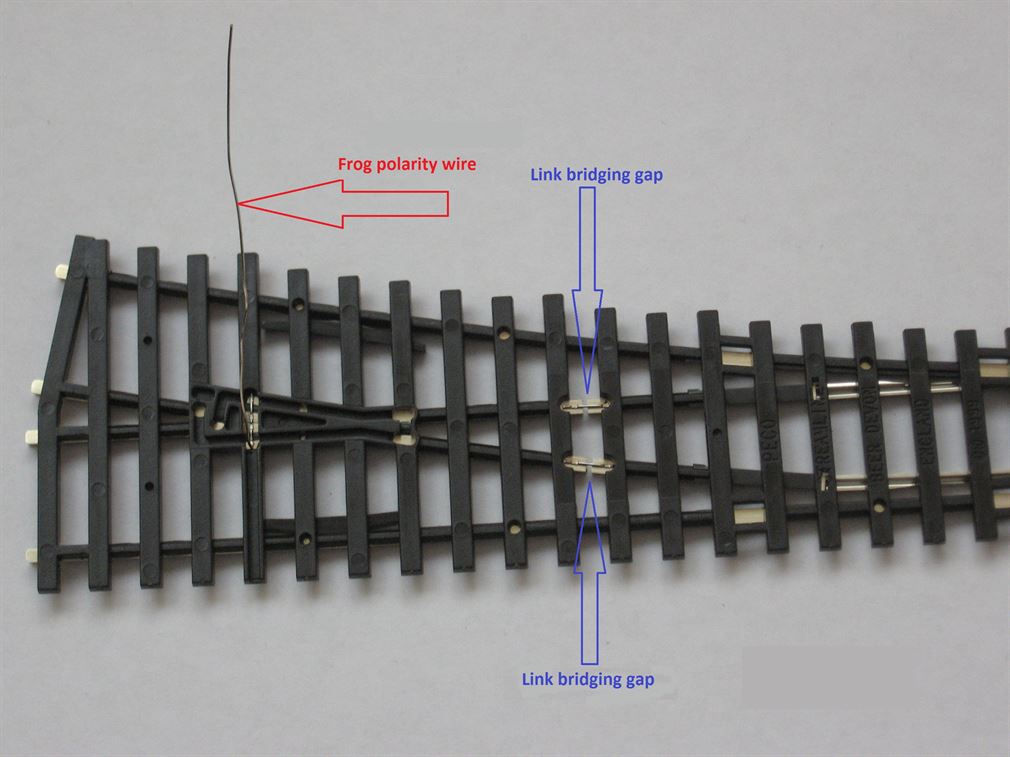
2) Short circuits caused by the metal wheels touching both rails at the frog. This is much more common on DCC fed layouts as both rails are permanently powered. This can cause the main control unit to detect the short and trip out. The problem of shorting is easily overcome by fitting two insulated rail joiners after the frog and for DCC layouts running in two linking wires from the two rails after the joiners and connecting them to there respective outer rails as shown in the diagram below. For DC layouts new feeds will be needed after the insulated joiners from the control panel and possibly via section switches.....
3) On DCC layouts, even if short circuits are not a problem, after the frog on any insulated frog point you should still install the two linking wires as mentioned in 2) above. These will ensure all tracks leading away from the point are then live and DCC loco's etc can then be shunted on a siding which has a point set against it, or smoke units, and any onboard lighting will remain on if wished. Alternatively, after the IRJs connect both Vee rails back to the DCC bus.
Electrofrog or live frog points such as the Peco Streamline range prefixed 'SL-E', those manufactured by Tillig, Marcway and many other track manufactures require a little more careful installation, as they will have to have a gap or Insulated Rail Joiners (IRJs) some know these as Insulated Fishplates, fitted after their frog and normally fitted onto the ends of the two Vee rails leading away from the frog. The reason is, as these points move over and back they swap electrical rail polarity on the frog and the two Vee rails if there is no means of stopping the power flowing out of the frog there is a risk of a short circuit occurring as a positive feed meets a negative.
Other than fitting the IRJs onto the frog Vee rails, nothing else needs to be done to allow the live frog point to work. That said, a large amount of live frog point users will opt for some means of electrically switching the frogs polarity and not rely just on the switch rail touching the stock rail for a connection. This is where the polarity of the frog and its two Vee rails up to the IRJs is controlled by a change-over (SPDT) switch, which is often a switch mounted onto the actual point motor. This then removes the sole reliance on the contact between the points moving switch rail and the fixed stock rail thereby improving electrical power feeding through the point. The wiring is shown in more detail in the Live Frog Switch Wiring section further down the page. However a viewing of the Video below may well help understanding how on a Live frog point the frog polarity is swapped over and the need for the two IRJs after the frog.
.
Below is a simple video showing how an Electrofrog (Live frog) point switches the track power between the two routes (Note: This does not occur with insulated frog points). Note that if the two sets of Insulated Rail Joiners after the frog where not used a short circuit would occur every time the points switch blade moves over and swaps the frogs polarity between positive and negative. i.e. The two rails leading away from the frog swap polarity (positive or negative) with each direction.
Shown below is a very simple track layout plan using Live Frog (Electrofrog) points. In the first drawing the points are all set for straight running or are in the 'Normal' position and three positive and return track feeds are needed. Note the Insulated rail joiners (IRJs) fitted after the frog Vee rails.
In the second lower drawing the points have all been moved to their 'Reverse' positions and now by comparing the two drawings it can be seen how the live frog causes the points rails after the frog to swap polarity.
In the third and right hand drawing, point number 3 has remained Normal while points 1 & 2 have moved Reverse.
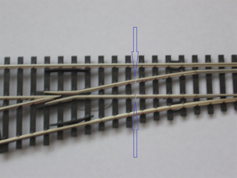
If the IRJs where not fitted after the frogs a short circuit would occur where the blue arrows are shown and a red rail meets a black rail.
UNIFROG. Peco have introduced a point called 'Unifrog' that is a mix of both Insulated frog and Electro frog. Peco are slowly rolling out this point in various gauges and it will take sometime (many years!) before all gauges are fully equipped with this choice of point. The idea is that straight from the packet the point is an Insulated frog style. The point is factory fitted with a frog wire which the Insulated frog user would usually ignore, however ideally the frog wire is taken to below baseboard for possible use later on (This then saves lifting the point in the future). The Electrofrog option is available via the frog wire and suitable frog polarity switching. Hence both styles are available in one point. In addition, the two closure rails are factory bonded to their adjacent stock rails and the closure rails are linked across to the Vee rail in the appropriate direction. The frog, which is of all metal rail and is as supplied electrically dead as it sits between four rail insulation gaps, except when the frog wire is used and then the frog is feed from a suitable means of frog polarity switching. The DC user when in the Insulated frog mode needs to be mindful that this point does not switch the track power off to the unset direction. Both directions from the point are powered regardless of the point blade position. If power route switching is required then the two factory fitted bonds joining outer stock rail to its adjacent switch/closure rail need to be removed. - Ideally undertaken before laying the point. But simply adding an Insulated rail joiner (IRJ) to form an isolated section is IMO best, rather than attempt to modify the point.
Below is a typical example of a Unifrog point...
Point Motor Wiring. Many layouts will use electric point motors, in my case I use Peco and Seep ones, but there are many other makes of solenoid motors available. They all work on the same simple principle. Apply a short burst of electrical power to a coil and an electromagnetic field is created. Place the coil around a tubular former and put a piece of iron (Iron core) inside the formers tube. Now when coil 1 is momentarily energised the Iron core is pulled across into that coils tube by the electromagnetic field created. Then apply momentary power to coil 2 - the opposite coil, the iron core moves across into that coils tube. Now fit a drive pin centrally on the iron core and connect the pin to the points moving tie bar and you have a means of electrically moving the point over and back.
The next item to consider is how these will operate and the wiring needed. I opted originally for stud and probe point control via my layouts mimic control panel, but I have since changed to sprung to centre off position toggle switches (On)-Off-(On) type. But there are several other methods of switching the point motor feed - Hornby R044 black lever switch or the excellent Peco PL26 are both passing contact levers and are just two of those readily available. Equally press to make non locking push button can be used, then two per point are needed.
For improved solenoid motor performance consider installing a Capacitor Discharge Unit. One Capacitor Discharge Unit (CDU) is normally used to feed the whole layouts point motors and this provides that extra pulse of power to move the solenoid motor, these are wired directly across the 16 to 24 volt point power supply transformers output. I prefer the use of 24 volt AC. for point operation via a CDU, but there’s no reason why the 16 volt AC. supply or any voltage ac or dc between 12 and 24volts couldn’t be used equally as well. Using a CDU reduces the current drawn from the transformer and also protects the solenoid motor/s coils from any possible continuous powering which can rapidly lead to motor coil burn out. So, I advocate always investing in a CDU, they actually cost little more than two new solenoid motors! They should be available from all good model railway shops or you can if wished make your own. Users of Hornby R044 black point levers please see notes later on re their incomparability with a CDU.
The drawings below show very simple arrangements of one point motor and either a passing contact lever, Stud and Probe or a switch - sprung to central off, and a CDU all powered from a 16v to 24v AC transformer. You will of course need to operate more than one point on a layout and all that happens is more studs or switches, Red & Green wires plus a return wire are installed. Touching the relevant stud with the probe allows the CDU to fire a 'one shot' discharge current through the appropriate stud and wiring and out onto the motors coil winding, or if using switches the momentarily closing of the switches contact operates the circuit. However, only passing contact, momentary or sprung loaded centre off switches must be used, otherwise the motors coil would receive full power continuously and quickly burn out, though a CDU will help to prevent this happening. When two or more sets of points are need to be operated at once, as is the case in a cross-over pair of points, then simply wire one motor onto the other, ensuring the electrical path for the two point motors direction is correctly orientated and wired on both point motors. Most CDUs can operate up to three or four motors simultaneously and those sold as "Heavy Duty" often can throw up to six or seven motors at once. Though I wouldn't like to do this, as quite high currents will start to be needed and the wiring probably will not allow such to occur (volt drop and current limitations). Anyway, why should there be any need for seven points all to operate at once? It's better to re design the circuitry and allow only two or three to operate simultaneously.
There are several other methods to operate solenoid point motors electrically than using the Stud and Probe or dedicated point lever switches. Push buttons of the 'push to make non locking' type are available quite cheaply and also Sub Miniature spring toggle switches of either the Double Pole Double Throw (DPDT) centre off type or Single Pole Double Throw (SPDT) sprung to centre off should type be used. I personally dislike push buttons such as the 'low cost Red or Black low cost Push button as they often ultimately tend to suffer with burnt-out contacts, however 'contact burn' isn't such an issue where a CDU is used. The sprung to centre off toggle switch is ideal, often called (On)-Off-(On) where the bracketed (On) cannot remain in that posisition once the toggle lever is released - it returns to the Off position under its internal spring. Using these toggle switches can be a quite cost effective means of switching solenoid point motors, especially when used on a mimic control panel - but watch out for any that may stick over one way and not return to the centre off position, as these will cause the CDU to remain discharged and prevent all other point operation requests occurring until the failed switch is restored back to its central off position, but the use of the CDU prevents coil burn out motor failure.
Below are shown three of the most simplest forms of electric point controls using a Passing Contact lever such as the Hornby R044 Black lever or the Peco PL26.


As previously, but now using the Peco PL26 Passing Contact Lever etc.

Below is the basic wiring configuration for both the Hornby R8243, the Peco PL11 and Gaugemaster PM20 surface mounting motors. Note that manufacturers use different coloured wires for their two operation and the return connections.
Below is a typical configuration where two solenoid motors are wired from one lever or switch. Often used where a Crossover pair of points need to move together. Note the wires form each motors operation feeds are taken to the one switch or lever. Note a CDU is not recommended for the R044 Black lever - see below for the reason.
Inside the Hornby R044 Black passing contact point lever switch.... (Not recommended for use with a CDU)
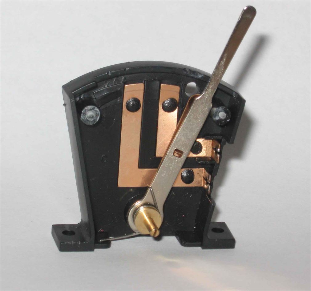
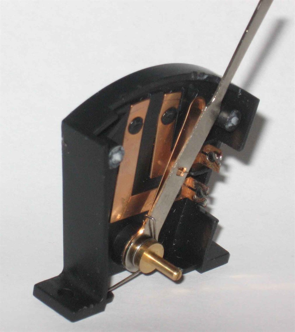
With the Hornby R044, power is taken into the lever switch via the central lower connection which also acts as the pivot for the lever, then as the lever is moved from its rest Off position it immediately makes connection On-1 with the first contact strip and sends power to the point motor coil, but this coil on the point motor is already in the point closed position, hence a little "Buzz" is often heard from the motor as the lever starts to move. Then as the lever is in its middle travel it is in the Off position. Next the lever makes connection to the opposite contact On-2 and provides an electrical path to the point motors other coil, powering the solenoid motor and moving point over. Finally the lever comes to rest and breaks the connection and is in the Off position at rest. So from one side to the other the point switch contacts are from Off - (On-1) - (Off) - (On-2) - Off. Note bracketed items cannot remain in that position. They are called 'Momentary' or 'Passing' connections.
The above 'double connection' produced by the R044 point lever is a problem where a CDU is to be used. As the CDU has to discharge into the first connection and motors coil (On-1) and then the CDU doesn't have time to fully recharge before the second and required contact (On-2) is reached.
In this case, it is advisable to hold the R044 lever in the central area of its travel for a second or two to allow the CDU to fully recharge before finally allowing the lever to be moved fully across the rest of its travel. Thereby allowing a the now recharged CDU to discharge via the passing contact (On-2) and energising the correct motors coil and moving the point over, before the lever finally comes to rest in the Off position.
The above 'double connection' arrangement does not occur with the Peco PL26 point lever switch, as this uses a totally different switching method and it only provides one momentary pulse of power to the correct motors coil during the levers full travel.
Below is typical switching using SEEP PM motors.
Below is the same circuit but this time using Peco PL-11 surface solinoid motors.
Above shows how two point motors are wired to one switch (or lever or two Push buttons etc) to allow both motors to move together.
Below shows a CDU (optional) feeding a bank of point toggle switches and then feeding out to the appropriate solenoid motors. Note: Wiring colours shown for wires may differ by each point motor manufacturer.
RETURN CONNECTIONS In the two drawings below, examples of point motors return wiring are shown, the upper drawing shows terminal blocks being used to allow individual motor return wires to connect together along a common return wire. In the lower drawing a common return wire is shown with each motors return wire connection being a twisted and soldered joint onto the bus wire. I would recommend where the common wire method is used to increase the wire size used to 32/0.2mm or use a solid copper wire such as 1.0mm2 or 1.5mm2 removed from former mains cable. Note: While Hornby R044 black point levers (passing contact lever switches) are shown, the principle applies to all types of point operation switches. Please remember the R044 lever does not work well with a CDU, but all other passing contact levers or momentary switches are fine. See this section for more detail on the R044 issue with a CDU.
Peco, Hornby and Gaugemaster have surface mounting point motors which resembles to some degree a real point motor. This motor comes supplied with three coloured lengths of wire attached. On the Peco PL11 and Gaugemaster GM20 the wiring colours are Red operation one way, Black operation to the opposite way and Green is the return wire. Below is show a PL11 wired to a passing contact switch, i.e. Hornby R044, Peco PL26 or a sprung to centre SPDT toggle switch and also shown is the alternative to these via a the use of momentary push to make (non locking) push buttons. Note: Wiring colours shown for wires may differ by each point motor manufacturer.
The basic wiring for multiple point motors and their switching is shown below. While five motors are drawn they are operated by four switches, more switches and motors can be added. Note the use of a CDU to enable better point operating performance. Where two motors are required to operate together e.g. a cross-over pair of points, then the two motors are be connected together and worked by one switch or lever as shown with the left-hand pair of motors. Note: Wiring colours shown for wires may differ by each point motor manufacturer.
The drawing immediately below shows a very simple Stud & Probe switching method. A CDU is shown, which I recommend. If the CDU is omitted (not recommended) then the wires from the PSU continue directly to the Probe and the other connection to the all the motors return connections. All wiring is ideally in at least 16/0.2mm (0.5mm2 or 20AWG).
Below is shown how the Stud & Probe can be fitted into the mimic panel facia and wires from each stud underneath the panel run off to the appropriate point motors coil. Note the recommended use of a CDU in the Probes feed. Where a cross-over pair of points are used, three studs are employed - one in each route. The two straight ahead route studs are wired together, so touching either one will power the two point motors of the cross-over 'Normal' (straight through running). The actual studs can be commercially available items or simply M2 or M3 round headed machine screws of suitable length, with a washer and nut fitted underneath. The wires to the motors coils are then either soldered to the stud or held in place by being sandwiched between a further pair of washers and a locking nut.
Momentarily touching the probes live end onto the appropriate stud supplies the power to that motors coil
One Wire operating method for Solenoid point motors only. By using a power supply that's capable of providing at least 1.5Amp or better if a higher amperage of around 3 to 4 Amps. is used along with an output voltage of at least 15v DC and a suitable electrolytic capacitor per point motor and two Diodes, the switching can move from momentary to always On using a Single Pole Double Throw (SPDT) switch. This style of switch if a toggle switch is used will allow the switches lever to indicate the position of the point its operating. Though not an actual indication that the point itself has moved out on the layout, only that the switch has been moved. A 1000uF to 2200uF electrolytic capacitor is used per point motor and this capacitor should have at least a rated DC working voltage of 35 volts or more. A pair of inverse wired diodes are used in the point motors operation feed. These I recommend to be 1N5401 3Amp diodes. All wiring throughout should be in at least 16/0.2mm equipment wire (0.5mm2 or 20AWG) or larger wire size.
Below is the basic wiring drawing. Warning; If you are not conversant with capacitors I recommend you do not use One Wire operation!
 (2017_01_23 23_11_49 UTC).jpg)
Below is shown the simple use of a four way piece of terminal block to make the diode and capacitor connections.
 (2017_01_23 23_11_49 UTC).jpg)
Stall Motors can be feed from either a 9 to 12 volt regulated DC supply or alternatively from a 14 to 16 volt or less AC supply. They work, unlike solenoid motors, by continuous power being fed to their internal electric motors. Once the motor has moved over the motor continues to draw a small current (typically no more than 5 to 15 milliamps) from the supply, this is known as the 'Stall Current' and this stall current holds the point motor over in the position selected. Note that this style of motor uses a panel switch to operate its motor that is always 'On' e.g. DPDT On-On toggle switch provides the required continuous supply to the motor. Ideally a regulated 12 volts DC or even a little less voltage (down to around 9v) is normally used as this allows the motor to slowly move over and back both more quietly and more prototypically too. They cannot be used directly from an AC power source, hence two diodes are fitted into the ac operation circuit at the bottom of this page.
Note the first drawing below refers to both the Tortoise make of motor and also the DCC Concepts Analogue Classic Ω motor. The feed/operation connections are to pins 1 & 8 on a Tortoise and 1 & 2 on a Cobalt. Pin 3 on the Cobalt is internally switched and offers a low current rated switched output ideal for LED panel indications via a suitable series resistor, as it takes its power directly from the motor feed inputs.
For DC power operation use DPDT switches and for AC power supplies on Tortoise motors use the two diodes and SPDT switches.
Below are the basic methods of wiring Stall type Motor Points..
All items appearing on this or any page of this web site are the intellectual property and © copyright of Brian Lambert. Unless otherwise stated.
You MUST NOT make available by placing them in any public domain area or in printed format any copies of Text, Image, Drawing or Video shown on this web site.
No item as listed above should be used, copied, linked to or forwarded by any third party without firstly obtaining the written permission of the web site owner - Brian Lambert.
You may freely and for personal use only, copy or print any areas.
You may refer to this web sites page electronic address detail (URL) in any other media - printed or electronic. Any such referenced URL should commence.... https://www.brian-lambert.co.uk/
Brian Lambert accepts no responsibility for any item appearing on this or any other page of this web site.
All items are given in good faith.
By visiting this web site you agree to accept and abide by all the condition shown above.