Hints & Tips

Below you will be able to find some helpful advice that should ensure your modelling goes that little bit smoother!
Baseboards Always ensure the baseboard, no matter what chosen material is used for the surface, is always well supported underneath. I would recommend that a grid of supporting timber be spaced at no more than 400mm (15 inch) centres and better still on a grid at 300mm (12inch) centres. This will over time give a rigid and sag free surface to support your railway.
A simple timber frame of 21 x 44mm (2" x 1") or deeper if wished PSE timber can be end square cut and simply butt jointed together. Use PVA woodworking adhesive and suitable wood screws to secure the framing. Intermediate cross braces are added by the same method. A hand operated mitre saw will give a good square cut if you're not overly good at carpentry or if you're likely to use one more frequently, then an electric mitre saw (Chop saw) could be purchased to cut the timber square.
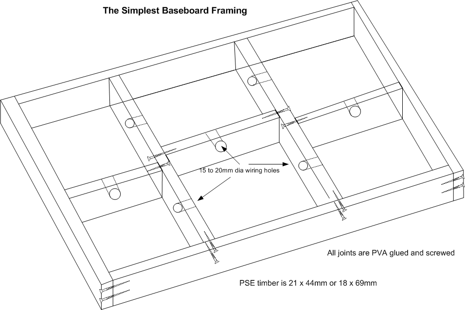
When using softwood (PSE) framing it is essential to purchase timber that is as knot free and straight as possible (warp free) then condition the timber prior to use. That is, remove any polythene covering and leave the timber for at least 48 hours in a dry room ideally where the final construction is to be located. This will ensure the timber takes on any moisture before its been cut and glued.
Before you fit the baseboard top remember to drill a series of 15mm to 20mm dia. holes on around a 25mm centre line from the top down and centrally in all internal cross braces. These holes will allow easier wire running to be undertaken once the top surface has been glued and screwed or pinned down.
Baseboard supporting legs should always be as ridged as is practicable to make them. For permanent layouts use (63 x 38mm) CLS timber fixed inside the corners of the supporting timbers. For portable layout up and under or free standing trestles can be used.
Portable Layouts If your layout is to be portable then one of your main criteria is going to be final individual boards size and weight. As you may end up carrying each board up or down stairs especially if your layout is to be of exhibition quality. Overall board size should really be limited to around a maximum of 600 x 1200mm (2' x 4' feet) after this it becomes a two person lift and is also quite unwieldy!
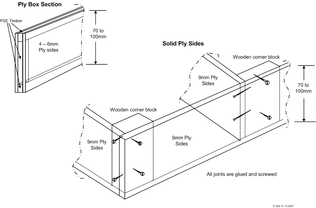
You can reduce board weight by using plywood as the underneath framing rather than the more conventional PSE timber used on edge, 9mm ply is ideal here but it must be at least 70mm deep or even deeper is possible. An alternative is to use 4 or 6mm ply and make this up into a box section with some thin (9 x 21mm) strip wood timber used top and bottom plus the ends and intermediately horizontally within the box section. This not only makes for a fairly light frame but is also immensely ridged too.
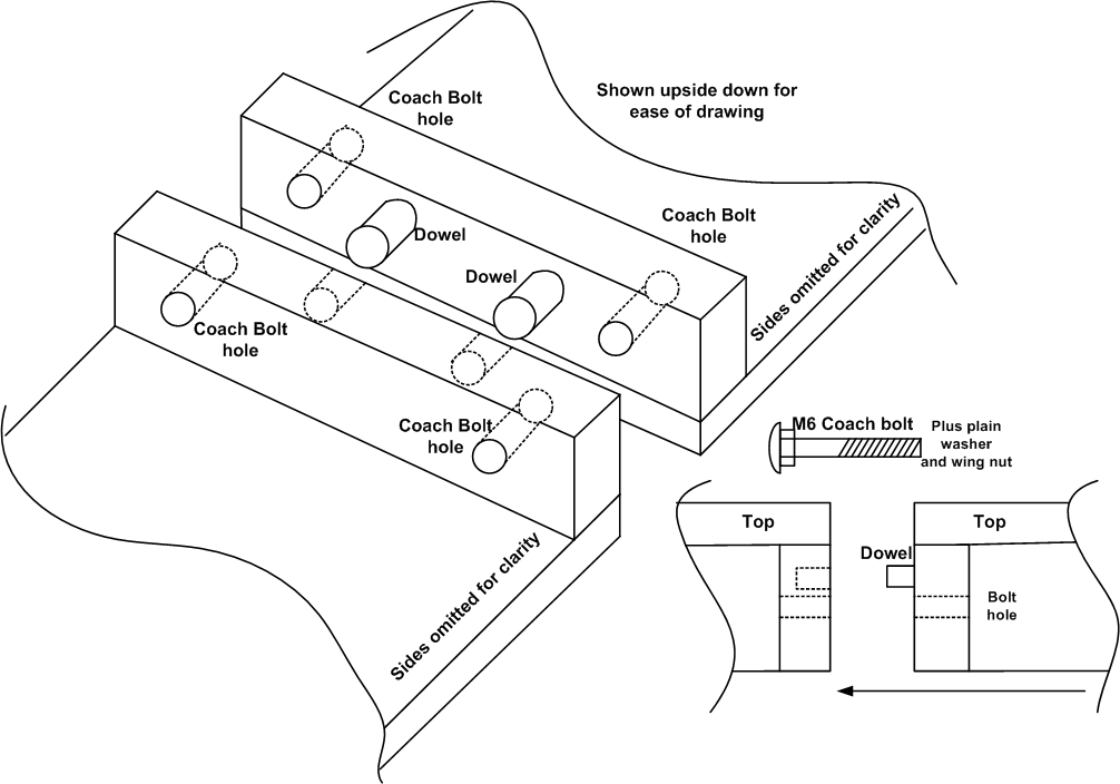
Portable boards will require some method of ensuring continual correct alignment and means of holding one board to its adjacent board securely. Alignment can be with nothing more than the aid of your eye and then tightening any through-board bolts securely, but a far better option is to use dowels. I like the very simple brass male & female types called 'Cabinet Makers Dowels' and all that is needed is a 7mm dia. drill bit and some PVA glue. Place the two boards together and temporarily hold in place with a couple of G clamps once you're satisfied the top surface and sides are all aligned. The drill right through from one side two 7mm holes around 50-60mm in from each corner. Release the G clamps and into one outer side glue then tap in the male dowel and into the other board glue and tap home the female dowels.
The method of holding two boards together can either be with two 6mm coach bolts passing through predrilled holes and then a suitable washer followed by a 6mm wing nut tightened up or by latches fitted on either side of the boards side panels. These just link across the two boards and when locked into position pull the joint up tightly.
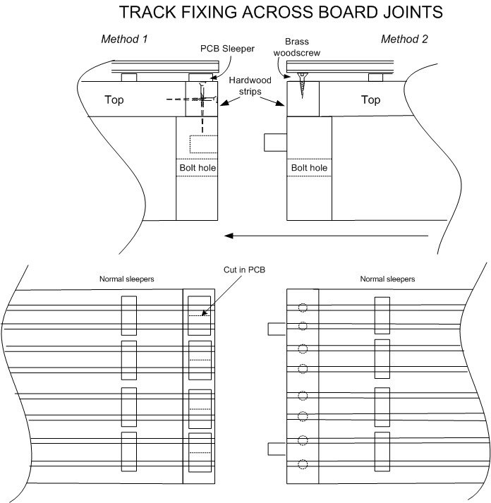
Track laid across portable board joints can normally be fixed and held securely in place by one of two well proven methods. Method 1) By using PCB sleepers and gluing and pinning or screwing the PCB to the end of the board you then soldering the rails to the copper PCB surface - Don't forget to cut a slit through the centre of the PCBs copper track to remove the short circuit that the copper makes to both rails. Method 2) Using small - No3 brass wood screws, drive each screw into the board until its head is just below the bottom of the rail, then solder the rail to the screw head. In both methods the track should be laid right across the joint, having firstly removed the required number of sleepers so as the track is free to be soldered to both board sides. Then each rail is soldered to both sides (PCB or screw heads) and then finally cut through directly in line with the boards joint with either a razor saw or an electric mini drill fitted with a suitable slitting disc. Once all the track has been cut through the two board can be separated and the ends of all the rails lightly filed to remove any burs etc. The drawing below shows both methods of rail fixing.
Note also the hard wood strip fitted to the ends of each board, this gives adequate fixings for the rails and a much harder end surface than some materials used for the boards main top may offer long term.
Both rail fixing methods are eventually masked by the addition of real stone track ballast.
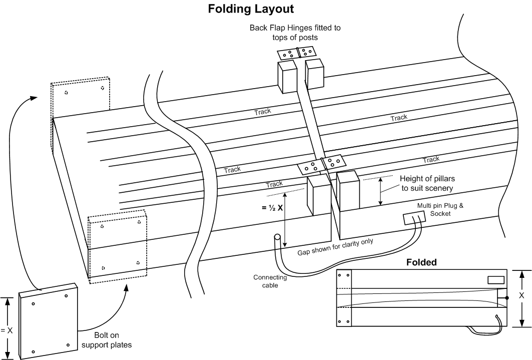
Below is a very simple twin folding board unit. More boards can be added to the ends and they also could fold in pairs themselves or they can be individual boards abutting onto the hinged opened pair. The height of the central pivot blocks is determined by the clearance needed once folded. This can be anything from 12mm to 70 or more millimetres. The pivot blocks and Back Flap hinges are hidden by suitable scenery, such as an over bridge, which simply drops into place once the boards are opened and secured. The size of both folding boards really need to be the same, but they can be of any length or width that's required and is practicable to physically lift and carry.
Note the use of a multipin plug and socket to take power across the joint. The number of 'ways' in the plug/socket is determined by the total number of functions needing to pass over the folding joint.
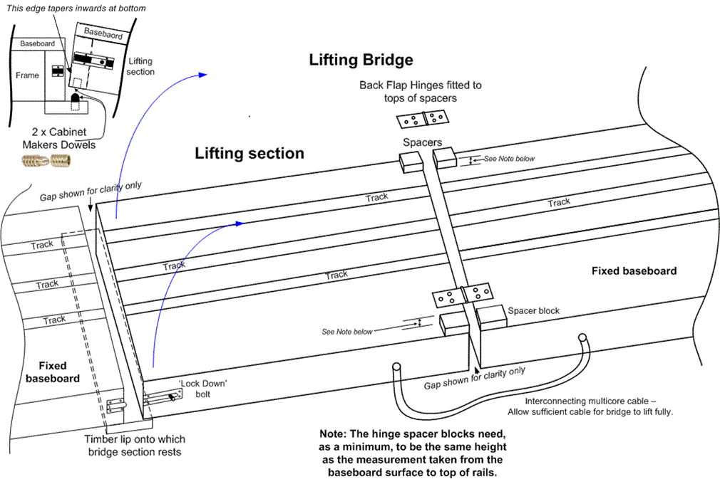
Lifting Bridge Section is often needed on fixed layouts to allow access to the central operating area or just for general access as it prevents having to crawl underneath the layout - Something appreciated by those of a more mature age perhaps! The bridge section is made in the same way as the rest of the layout. e.g. Conventional PSE timber is used to make a ridged framework topped with the chosen baseboard surface. The section is a close but not dead tight fit between the two fixed baseboards either side and is hinged at one one end allowing an upward pivot to take place. The Back Flap hinges (or Butts if preferred) are screwed down either side of the baseboard. They need to be fitted onto small spacer blocks to raise the hinges above the baseboard surface. The spacer blocks are at least the same height as the measurement taken from the top surface of the baseboard to the top of the rails. These then allow the the bridges rails to clear the fixed ones as the bridge is lifted upwards. At the other fixed baseboard side a suitable piece of PSE timber is screwed to the underside of the fixed board to act as a small lip onto which the bridge rests when lowered. Into the lip and the underside of the lifting section are installed a pair of Cabinet makers dowels to ensure full and secure alignment when lowered. A simple sliding bolt locks the bridge down. A suitable sized multicore cable or individual flexible wires connect the fixed hinged side baseboard to the bridge span and carries all track power needed for the bridges tracks, remember to leave sufficient slack in the cables or wires to allow for the bridge section to hinge upwards without over tightening the wires or cables.
Power connections across the bridges gap can be arranged from one fixed baseboard to the other fixed baseboard. This can be via multicore cable(s) running from one sides fixed board, passing across the gap and onto the other fixed board. e.g. the cable is run around a door frame etc. Or alternatively these feeds can be distributed around whole of the fixed layout sections ending up at the further fixed board after the lifting bridge section. The choice of how these feeds are supplied is the layout builders.
Below is a simplistic example of how the bridge section is hinged, aligned and locked down etc.
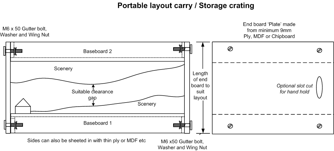
Storage and transportation of portable layouts can be improved by placing two identical sized baseboards scenic side to scenic side with a suitable gap between the two scenic faces and then holding the two boards secure with the aid of two end plates made from Ply, MDF or Chipboard. Use 9mm board for the end plates as a minimum. M6 'Gutter bolts' approx 50mm long or of length to suit your framing thickness, are passed through the end plate and through the baseboards framing and then held secure with a M6 washer and M6 wing nut (2 per baseboard end).
Track laying. While I'm actually using "00" Peco Streamline code 100 track these tips should apply to any type or gauge of track.
Firstly draw in pencil a straight line on the baseboard in the middle of where the track is to be laid, this will give you a guide as to where the actual track is to be positioned. Then, to ensure your main line tracks are nice and straight use a steel rule, ideally a 2' foot or longer one, and place the edge of the steel rule against the outer edge of the rails web. By ensuring all the length of the track is gently pushed up to the edge of the rule a dead straight track length can then be lightly pinned in position. Once fully pinned, move the rule forwards onto the next section, but keep around 150 mm or 6" or so still in contact with the first section laid as this will ensure your track remains straight throughout its entire length.
When pinning the track down, like to use the Peco track pin, as it is a very fine pin and comes pre blackened and it has a small pin head too which isn't that obvious if left in place after ballasting. However, trying to push or drive the pin through the sleepers and into the baseboard is quite often problematic as the pin easily bends and then becomes useless and has to be pulled out and discarded! I recommend pre drilling a fine hole dead central through the sleeper and just a little way into the baseboard. An Archimedean hand drill is the ideal tool here or an electric mini drill. However, I find the very fine drill bits needed easily snap and are quite expensive too. So here's a little tip I have found very useful....Cut off the head of a Peco track pin and place the pin into the drills chuck. The pins sharp point will then drill through the sleepers and into the baseboard giving a nice starter hole for the actual track pin to pass through. When eventually the 'pin drill bit' bends or looses its sharp point simply discard it and use another pin. Cheap and effective hole making!
Fold up layouts can be made to around a maximum front to back measurement of 4feet (1200mm). The two reasons for this restriction are:-
1) When folded up the layout will be almost to the underside of a conventional ceiling as the baseboards lowered height needs to be around 39 inches (1000mm) above floor.
and
2) To reach a piece of stock that is close to the wall, the maximum 'reach over the layout' is really no more than three feet and even that is pushing the limits of a persons reach!
Length can be whatever is chosen and fits the available wall space.
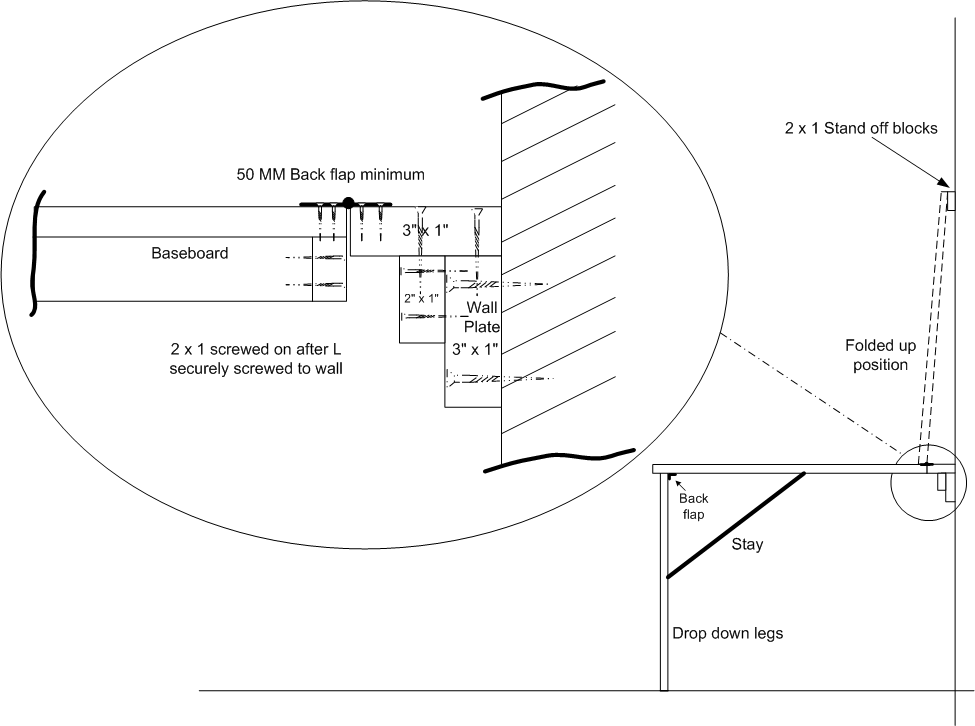
The wall plate timber, which I recommend to be made from at least 3" x 1" (69 x 21mm) PSE timber, must be securely screwed to the wall and be level throughout its full length, which will be the same as the layouts length. Onto this is securely glued and screwed a similar 3" x 1" PSE full length timber onto the top of the wall plate and finally secured by a piece of 2" x 1" (44x 21mm) PSE glued and screwed up tight to the internal L shape to produced an additional brace to the L construction.
The main layout boards are constructed in the usual fashion, with a chosen baseboard top and securely braced underneath with a minimum of 2" x 1" PSE or a ply box etc. on a square grid ideally at 15"(400) centres The baseboard is then hinged from the edge of the top 3" x 1" 'L' bracket by at least four 2" (50mm) back flap hinges.
A set of drop down legs, which are also hinged with the aid of back flaps, are fitted onto the two outer corners and if necessary a central leg mid way long the front edge too can be used to give added support. These MUST be braced to the baseboard to prevent accidental movement of the legs back under the board when lowered. The braces or stays can be a smaller dimension timber or made preferably from flat steel bar. These stays are held in place by No 10 gauge round head screws as shown in the lower diagram, the stay then clipping over the screw heads. Alternative a smaller layout could be lowered and rest on top of a cupboard e.g. a chest of drawers. In which case the 'L' wall plate is fitted at the same height as the chest top.
Once folded up against the wall note that the baseboard has a slight angle inwards towards the wall to help maintain it in the up position. The layout touches against a small wall plate made from 2" x 1" timber and I recommend a sliding bolt be used at both ends to secure the baseboard when fully raised.
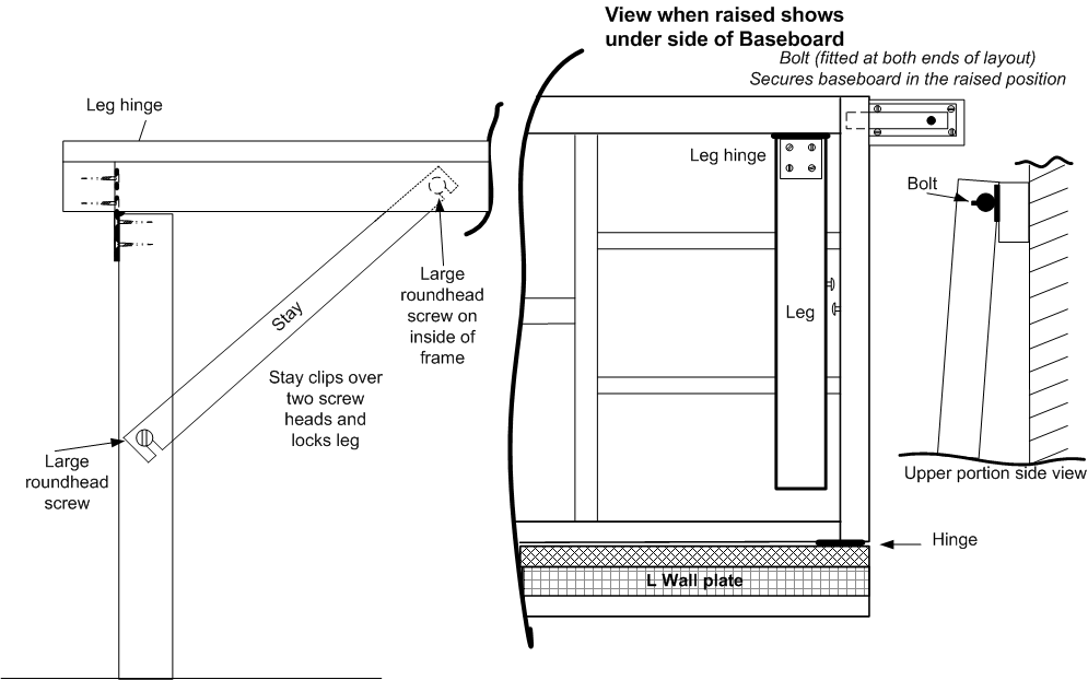
On larger fold up boards it may be desirable to have a simple form of rope and pulley system to enable easy and controllable lowering and also to aid the raising of the board to its upright position.
The only disadvantage of the fold-up baseboard is that all rolling stock and virtually all buildings etc have to be removed before it can be stored upright, as there is very little clearance between the wall and the raised surface of the baseboard. This 'setting up' and 'putting away' time has to be added to every running session!
Back to Back wheel gauge (B2B) should be checked with the aid of a specially made gauge block, This will give the correct distance between the two inner faces of the flanges of all rolling stock. You should check and adjust if it's possible to do so, all wheels on a loco including those on any pony trucks and bogies plus also all the wheels on your coaches and trucks. The B2B gauge for standard "00" is 14.4mm+/- 0.05mm and is set by the UK's The Double O Gauge Association.
You can buy gauges directly from the Association by visiting their shop at The Double O Gauge Associations For "00" you would need their ''Intermediate standard" gauge for UK OO. Or they can sometimes be purchased from some good model shops, just be sure you purchase a 14.4mm to 14.5mm one.
While this checking is being carried out, take the opportunity to remove any deposits of dirt from the tyres of the wheels, that all so easily builds up during running. Do this with the aid of a fibre pencil, an old small flat bladed screwdriver or a specialist brass wire brush. Then follow up with a Lint free cloth (old cotton hankie perhaps?) soaked in a little Isopropyl Alcohol (IPA) 99.9% variety. Alternative can be to use Methylated Sprits (Meths) and rubbed onto the wheels, or use a cotton bud to apply the fluid. Please ensure safety measure are in place when using these fluids mentioned - strictly No Smoking and have a well ventilated room. Consider too replacing any plastic wheels with metal tyre ones, as the plastic wheel is renown for spreading dirt and grim from its wheels onto the rails, resulting in even more rail cleaning being needed.
UK railway terminology explained...
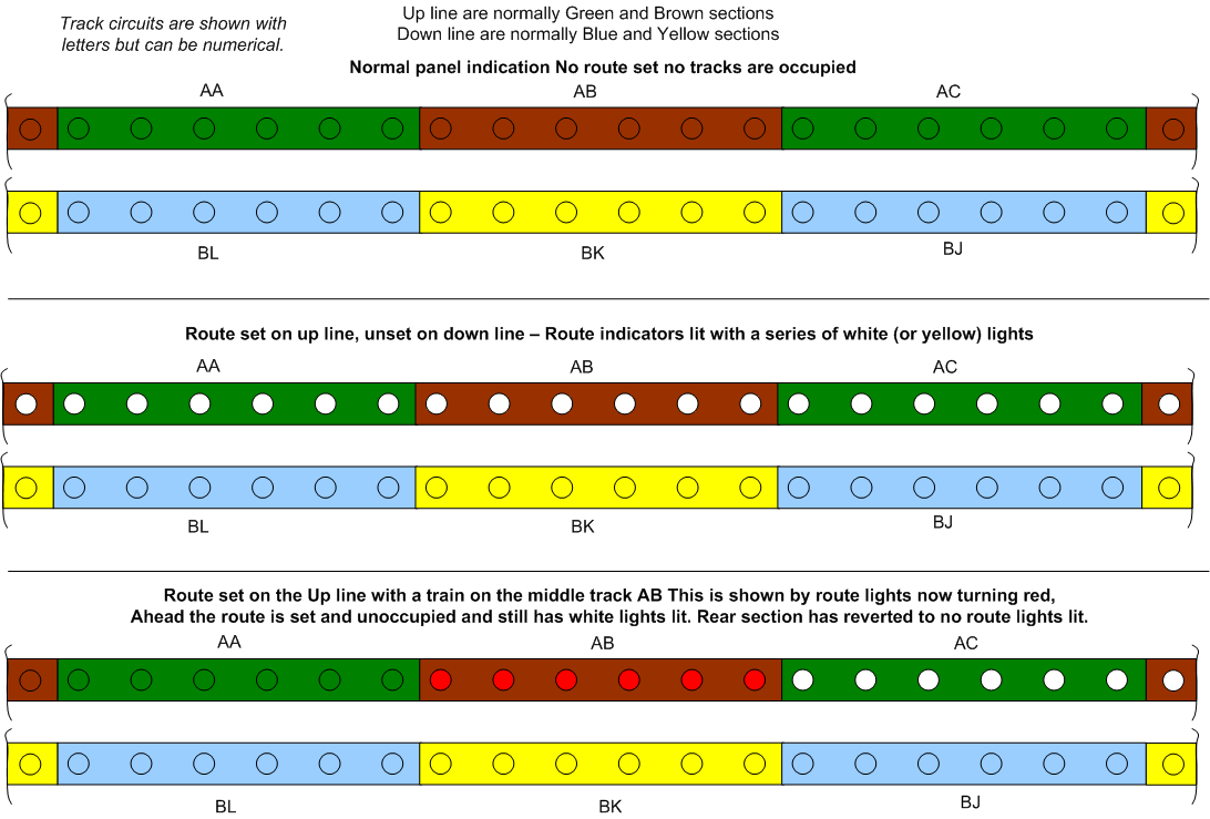
Up Line Nominally the line that traffic proceeds along towards London. But there are many exception to this rule!
Down Line Normally the line that traffic proceeds along away from London. But as per above there can be many exceptions.
4 foot The gauge or spacing between two running rails. Standard gauge is 1,435 mm (4 ft 8 1⁄2 in) Measurement is taken from the inside face of the running rail.
6 foot The space between two adjacent running lines. i.e. an Up & Down line would have a nominal distance between the two lines of 6 feet.
10 foot The spacing between two adjacent lines where there are more than two parallel lines. Often found between the middle tracks of a four track railway. But can be used elsewhere too.
Point Known as a Turnout. The means by which a train is routed onto or from another routes direction.
Switch Rail The moving 'blade' of the point that can be moved and closed tight against the stock rail to allow the wheels flange to be guided into the set routes direction.
Stock Rail The outer most fixed rails of the turnout.
Crossing Known to the modeller as the 'Frog'. This is actually the Common Crossing where the rails converge to allow the wheels flanges to pass onto the next section of track after being routed by the closed switch rail.
Stretcher Bar The normally made of metal strap used to connect together the switch rails.
Check Rail A short length of rail fixed to the inside the running rail. Its use is to guide and push the trains wheels flanges towards the running rail. Fitted only in a specific areas and typically used on all points directly opposite the crossing (Frog).
Route The direction required.
Point Normal The points is set for the main directions route. In most cases this is the straight ahead direction But this cannot be taken for granted as Normal can be to the turnout direct too.
Point Reverse The opposite route direction to the Normal.
Point Detection The means of proving the switch rail is correctly closed onto its stock rail. Can be mechanical or electrically proved.
Signal On A signal set to danger or in the case of a distant signal set to caution.
Signal Off A signal set to proceed. The aspect shown on colour light signals can be a single Yellow, two Yellows or Green etc.
Braking Distance The required distance needed from whatever the maximum line speed is to reach stopped.
Signal Box A building from where train movements are controlled via the signals and points. Can have levers or an electrical panel.
IECC Integrated Electronic Control Centre. A signal box, but where all the signalling controls are operated by electronics.
Level Crossing An area where the road crosses the railway. The road user is often protected from the railway by means of gates or barrier booms.
OHLE Over Head Live Equipment. This is the high voltage overhead electrical supply items used to power the trains motors. Power is collected from the OHLE wire and transferred to the locos control equipment and into the electric motors
Pantograph The sprung arm that is fitted to the top of the locomotive or train. It touches onto the underside of the OHLE contact wire to collect power to the trains electrical systems including its traction motors. Nominally 25,000 volts ac in the UK and many other countries.
Third Rail A third rail that is positioned to the outside of the running rails and is used to provide power to the trains electrical systems including its traction motors. Nominally at 750 volts dc.
Semaphore signals.....
UK Semaphore signals have two main styles of signal arm. Red arm with a white band which when horizontal means stop. Raised (or when lowered on some regions) to approx 45 degrees from horizontal means Proceed to next signal.
Yellow fishtail arm with a black chevron is a Distant arm. This can be passed with the arm in either straight or raised (or lowered on some areas) positions.
Red arm horizontal ... Stop, at or just before this signal. Red arm raised (or lowered) by approx 45 degrees... Proceed to next signal, which may be at stop.
Yellow Distant arm horizontal...The next signalling ahead is not cleared to proceed, be prepared to stop at the next signal. Yellow Distant arm raised (or lowered) to approx 45 degrees in conjunction with the red arm being raised (or lowered) if there is one on the same post. The whole section ahead is cleared - All section signals ahead are at a proceed that are controlled by the signal box for that section.
Semaphore signal arms can, depending on their operating region, be either raised to approx 45 degrees from the horizontal (known as Upper quadrant signals) or lowered from the horizontal to approx 45 degrees (known as Lower quadrant signals) giving a proceed indication to the driver. Both lowered or raised positions mean the same. You would not expect normally to see a mix of the two type in the same signalling area. 'Section' is the whole area normally controlled by one signal box technically the Block Section.

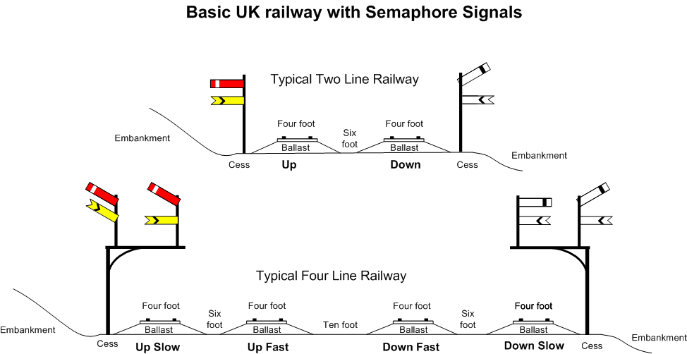
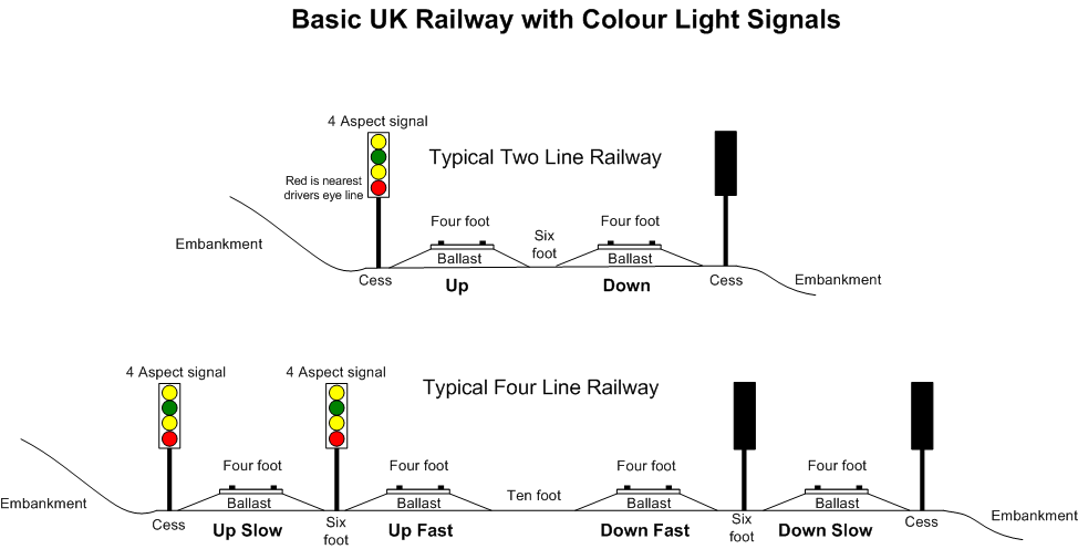
Above shows....
2 line railway..
Up line is at danger - train must stop at this signal.
Down line train can proceed past this signal, but should be prepared to stop at the signal ahead.
4 line railway..
The Up slow line has all signalling ahead cleared to a proceed.
The Up Fast line train can proceed past this signal, but should be prepared to stop at the signal ahead.
Viewed from the rear...
The Down slow line train can proceed past this signal but should be prepared to stop at the signal ahead.
The Down Fast train must stop at this signal.
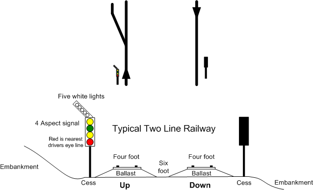
Track plan for below
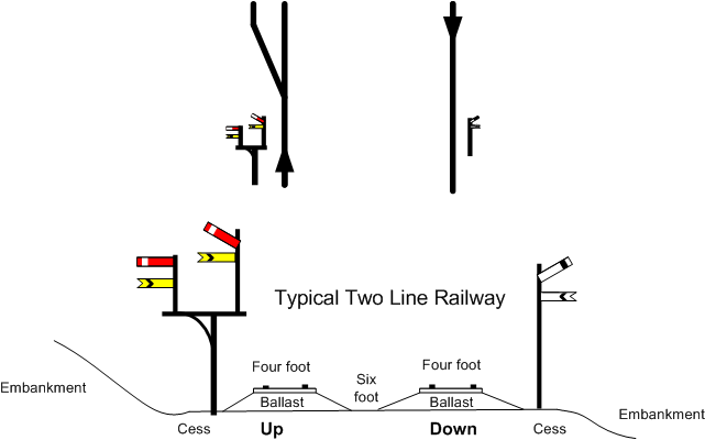
In the above drawing, again a two line railway is depicted, but the Up line signal is now offset to the left of the tracks called a Bracket. The right-hand post on this signal is taller than the left hand post. The taller one representing the main route while the lower one is for a diverging route off the main route. So in the example shown above, our approaching train driver is advised that beyond this signal is a left hand junction (point). The signalling is telling the driver that the straight ahead route is set and a signal ahead is not cleared to proceed, so be prepared to stop at this signal.
If the signal arms on the right-hand longer post were horizontal and the left-hand stop (red and white) signal arm was raised (either the red one on its own or with the yellow distant raised too) this would mean that the point ahead is set for the left-hand diverging route direction.
Colour light signals...
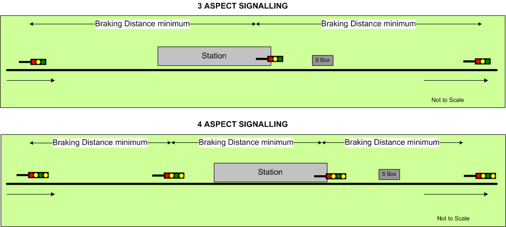
In the UK the aspect nearest to the drivers eye line is always the Red, which on post or gantry mounted signals is the bottom aspect. Above the Red is the Yellow and above that the Green. On four aspect signals there is a second Yellow aspect which is placed above the green and is lit only in conjunction with the lower yellow, never on its own. LED lit signals are replacing filament lamp lit signal heads and LED signal heads have one lens with triple colours, that is to say the one lens is capable of displaying all three aspects - Red or Yellow or Green. Where a second Yellow aspect is required then a single LED lens is mounted above the first triple lens and this top lens can only display the Yellow of the second yellow aspect sequence.
Colour light signal aspects mean.... Red... Stop. Lower and first Yellow.. Caution next signal ahead is at red. Lower Yellow and top Yellow both lit...Start to slow, next signal is at Yellow and signal beyond that is at red. Green... Line ahead for the next two signals are at proceed on four aspect signalling and the next signal is at a proceed aspect on three aspect signalling.
Below is shown simple UK colour light signalling. The two drawings with a green background show the two main types of colour light signalling 3 and 4 aspect. 4 aspect signalling is used where more density of traffic is required to use the same section of line. The lower set of sketches show the same track layout as used for the semaphore example above, but colour light signals have replaced the semaphores. In the very bottom sketch the Up line signal is protecting the facing junction point some way ahead of the signal. This time the colour light signal is fitted with a five white light Junction Indicator, also known as a 'Feather'. This only illuminates when the left-hand route through the point is set and the main signal is displaying a proceed aspect. It does not illuminate with the red aspect displayed. At some locations it may be possible to see the Junction Indicator lit and the main signal at red, caused by the remote interlocking sorting out the route and the main signalling controls. So the signal is waiting for command to step up to a proceed from a red aspect .Typically this is frequently seen on modern IECC/SSI interlockings. Rules prove the route is set the aspect can change. So by the time the route set acknowledgement is sent back to the IECC via the SSI the J/I has been lit for a few seconds with the main aspect at red. (SSI is Solid State Interlocking and IECC is Integrated Electronic Control Centre - A modern signal box using computers and VDUs)
Typical Filament lamp lit 4 aspect signalhead.
Typical LED 4 aspect signalhead.
Image Curtesy of unipartdorman.co.uk
Note: On LED signalheads the lower aspect is able to display Red, Yellow and Green while the upper aspect displays the 2nd yellow aspect only.
Note the terminology used... Cess has already been described above and is the area to the left and right of the tracks. 'Four Foot' is the name given to the distance between the inside faces of the running rails (Actually 4' 8½" or 1435mm). 'Six Foot' is the term used to describe the nominal distance between two adjacent tracks. 'Ten foot' describes the wider distance between tracks and one 10 foot is normally found on four track railways. 'Ballast' is the stones that retain the track at the correct level and prevent the sleepers, which the rails sit on, from moving together or sideways. 'Sleepers' are the Wood, Concrete or Steel beams that the rails and their fixing are held in place by. The rails sit in specially shaped 'Chairs' which are in turn fixed to the sleepers. Two types of rail exist - 'Bullhead' and 'Flat bottom'. Bullhead is now virtually extinct on UK main lines and can now mainly be found in some sidings and on preserved railways etc. Flat Bottom rails are used on virtually all UK main lines and often this is of the 'Continuously Welded Rail' (CWR) type where long 600 foot lengths of rail are laid in place of the older 60 foot jointed lengths. The 600 foot lengths of CWR are then welded into even longer lengths on site to make an exceptionally long rail length. Special expansion joints are used at set distances in the CWR to allow for temperature changes causing expansion or contraction within the rails.
As stated previously, there are always exceptions to these basics and if you're modelling a specific location or time period you will need to carry out research to find more about what was used at that time or place etc.
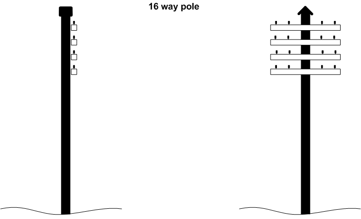
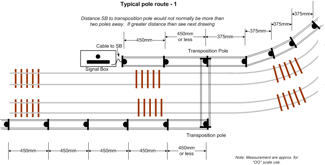
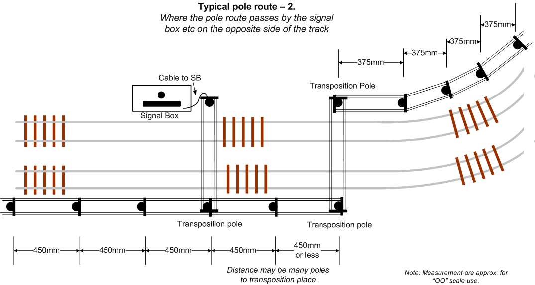
Telegraph Poles and their wires were the means of the UK railways being able to communicate from one place to another. The wires which were often open copper wire, though some pole wires had an outer insulation, were suspended on the pole route and they carried telephone circuits, signalling block working controls, Block bells for signal box to signal box train details, signal control circuits and at times the power supplies for remote signals especially colour light distant signals which were battery powered and the batteries charged from the power supply.
Poles were mainly spaced at approx. 60 - 65 yard intervals along the straight and they were positioned closer together on curves to approx. 50 yds minimum apart. On a curve, the pole route was whenever possible run around the inside of the curve.
The poles and their wires were installed so as minimum clearances was achieved - over the railway the minimum clearance was deemed as being 17 feet above rail top. At a rural crossings 16 feet above the road surface and when passing over a main road the lowest wire would be at 20 feet minimum above the road.
Where the pole route needed to cross the railway, and this would be avoided as much as possible, a ‘Pole Arm Transposition' pole is used. These have conventional arms for the wires coming in and more arms set at 90 degrees to the normal ones. These extra arms carry the wires over the railway. Pole arm transposition poles are by their nature are normally quite tall to allow the lowest wire to be at least 17 feet minimum above the rails.
Note; to confuse matters, the actual wires on the pole route were also Transposed at around every mile or so to help prevent inductance which could lead to overhearing on a telephone circuit or worse one circuit electrically effecting another. Here Transposition poles are often referred to. On these the wires on for example the top arms outer side were connected to a lower arms inner side or at times they simply be crossed from one insulator to the other on the same arm - Transposing the wires.
Pole arms where usually arranged to be on the ‘London’ side of the pole except for terminating poles. Though I'm sure there are many exceptions to that.
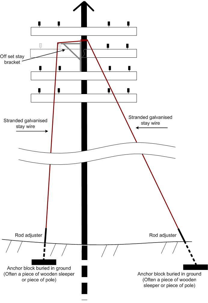
Where poles are acting as terminators or are on a curve, stay wires are added to help prevent the pole being pulled over by the tension of the wires. A pole can have one to four stay wires (Or even more if required!) They would be placed at 180 degrees opposite the wires 'pull' direction.
Stay wires, which are of a galvanised stranded wire, are attached by a loop of the stay wire wrapped around the poles near top portion, but the actual position depends on the amount of arms and wires attached to the pole. The stay wires running, whenever possible, directly from the pole to the adjustable tension rod which emerges from the ground, the stay wire being at approx 30 to 40 degrees from the poles vertical. Where the adjustable tension rod cannot be accommodated at a suitable distance out from the poles base - due to the track, embankment or a building etc then an off-set bracket arm is attached just below the stay wires fixing loop and this then forces the stay wire out at near 90 degrees from the pole then via a loop or U shaped channel in the end of the bracket the wire drops almost upright at around 10 to 20 degrees to the pole and runs down to the adjustable tension rod at ground level.
Most poles would have a soft metal - Lead or Zinc cap fitted to help prevent the pole from rotting. Pole steps are normally fitted from around 10 - 12 feet above ground to just below the lowest arm these alternated on each side of the pole and quite often the last top step had a diagonally mating step too.
The wires being held in place by mainly white Porcelain insulators though some insulators made from a black compound can be found. Red insulators are often found on the lower outer positions carrying power - Typically 110 volts for powering line side items such as battery chargers on a distant colour light signal.
Initially Pole Climbing Irons where used by railway staff to climb the first portion of the pole. These were worn by the Signal & Telegraph staff when accessing the pole wires. But Climbing Iron use was withdrawn around the 1960s and it became necessary to use a special a Pole Ladder often a two section wooden ladder, to access the first pole step. These ladders had a curved metal fixing at their tops which sat onto the pole and gave more support to the ladder. Sometimes the ladders curved metal straps were replaced with a stranded wire strap which sat partly around part of the pole when the ladder was in place against the pole.
Modeller using 4mm/foot (UK OO) means the poles would be placed approx. 780mm apart! I find personally placing them closer together looks much more correct and I have found that a 400mm to 450mm spacing is about correct
======================================
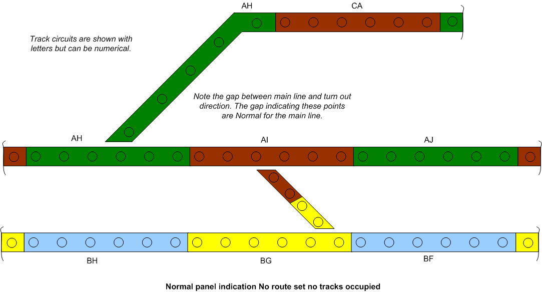
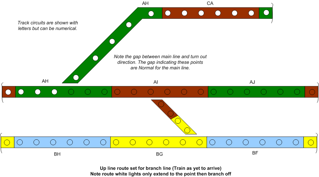
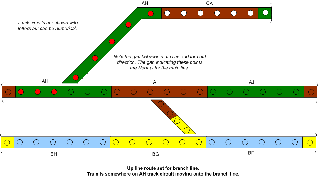
Below is a section with up line branch and a cross-over up to down lines
Scenic scatter.... My method of applying and bonding scenic scatter materials is to paint the base a dark brown colour with acrylic or poster paints. Leave to fully dry at least 24 hours. Then coat the area with neat woodworking PVA adhesive – any cheap make will do. Then sprinkle on a mixture of various shades of brown and green scatters. I also use foam scatters too, as these tend to be more like rough areas of grassland.
Once satisfied with the overall appearance, I then and with the aid of an old, well washed out, kitchen sprayer bottle, mix up a dilute amount of 40/60 PVA / water with a tiny drop of washing up liquid or Meths added. This mixture is misted over the whole area and left again for a minimum of 24 hours to dry – longer if possible.
Then with the aid of an old clean pop sock or tights leg tucked inside a vacuum cleaners nozzle and held around the outside, I vacuum up all the unstuck scatter and foam etc. It is collected for reuse in the old pop sock which is, once the hover is turned off, pulled out of the nozzle and empted into a ‘Mixed scatter’ container.
There will be some areas that didn’t stick, so now apply with the aid of a artists or modelling paint brush some more neat PVA to the bald patches. Sprinkle some scatter from the ‘mixed scatter’ container onto the neat PVA and leave to set. At this stage you can add scenic clumps, trees or bushes etc all bonded to the scatter or baseboard with the neat PVA. Tip - around tree bases apply a little neat PVA and add some more ‘mixed scatter’ around the area, this will help hide the tree trunk join to the scenic’s or baseboard area
Ballasting.... You must be 100% sure of the track plan and also ensure smooth operation is all correct and also test the area of track is correct electrically, before ballasting. Otherwise, if errors are found after ballasting it is virtually irremovable! But this is the finish needed to retain the track.
My track is lightly pinned directly to the baseboard, which is 9mm WBP Plywood. No cork is used. Once I have finished wiring, I then test with as many locos and various types of rolling stock as practicable to ensure it's laid correctly and allows good running.
Having ensured good running, I then paint the rail sides. I use a special roller and paint sold under the brand name of "Rusty Rail Painter". It so easy to use, if you Google the name you should find a demo video of it being used. You can equally use a small paint brush and Humbrol or other make of paint. **See the note below about point blades tape. As soon as the paint has been applied I then use an old lint free cloth dampened with a little white spirit to wipe the rail tops and the inside upper edge of the rails clean. Once ballasting has been completed I clean the rails with a track rubber followed by regular maintenance programme of Isopropyl Alcohol (IPA) applied via a lint free cloth. I also have a CMX tanker track cleaning wagon which is pushed around in front of a large loco and this applies the IPA to the rails and cleans them.
I have used ballast produced by a company called Javis, which is sold in large 7lb bags, but the Woodland Scenes range is a very good choice too. I use a mix of fine and fine-medium in the proportion of 4 to 1 (4 fine to 1 of fine-medium). You may prefer to use only fine ballast! It's really a personal choice. But it's a rule of thumb to use ballast in a size smaller than you're modelling in. i.e. "N" gauge or fine ballast for "OO" etc.
I apply it with a teaspoon, used like a mini shovel. Carefully tipping a layer of stones along the centre and both outsides of the track. I then use a wide Artists/Model type paint brush to gently move the stones into their correct position, sweeping forward all surplus stone. When sweeping ensure all stones are removed from the inner rail sides and sleeper tops. Any surplus is either removed by sweeping it onto a piece of paper or carefully added to the end of the area being ballasted.
**On points I apply a tiny strip of masking tape to both inside faces of the point blades - switch and stock rails, where the two would normally touch (before painting the rails) this is left in place until ballasting is completed. I also carefully remove any stones that have got in between the check rails and the running rails and also the frog area. Check too the open switch rail side is clear of stones.
Next I mix some woodworking PVA glue (cheapest brand I can find!) with water 40/60 (40 parts PVA / 60 parts water) and add a drop of washing up liquid or Meths to help remove surface tension. Shake or stir the mix well.
I have an old plant mister bottle, but a well washed out former household cleaning spray bottle (as used originally to spray kitchen worktops etc) is also ok. I fill this with plain water and add a tiny drop of washing up liquid (WUL) or Meths. Note Meths can be substituted for the washing up liquid as Meths as an excellent surface tension reducing agent.
Now that the ballast is all in the correct place and your satisfied I spray the area with the water and WUL / Meths mix to dampen the ballast. Then using a Pipette I apply the glue/water/WUL mix to the ballast, so as the whole area is soaked. At this stage do not touch the ballast.
Wait at least 24 hours and better 48 and then hoover off any unstuck ballast (there is always some that fails to stick!). Go back with the teaspoon and add a small amount of new ballast to the bald area(s). Apply a drop of the glue mix to bond it and wait again at least 24 hours. Then follow up with a second gentle hovering.
.
If points are involved in the ballasted area, I try to move them over and back several times during the drying period to ensure no glue has got into the point. Obviously this is only done during the fist couple of hours or so as it's not possible to do this overnight or while at work etc.
If you used track pins to hold the track, now is the time to remove them. I now use a track rubber to remove all tiny bits of paint and certainly some glue from the rail tops. Once the rails are clean, hoover again to remove all bits of glue/paint scrapings and any track rubber residue etc.
Next, I use an old four wheeled wagon and run it by finger over the area. It should be felt to run along all the tracks without any binding or bump/bumping. If there is any, then look to see what's causing it - Normally a small piece of stone is glued to the bottom of the rail, which can be levered off with a small flat blade screwdriver etc. Remove from the track the offending stone - It can if left on the track, get into the locos gearing etc and cause serious problems
Rail maintenance..... I use and recommend rail cleaning via a track rubber or the rough side of a piece of small off cut of Hardboard (Masonite in the US) initially, then follow up with regular periodic maintenance using Isopropyl Alcohol (IPA) applied with a lint free cloth (Old cotton hankie etc). Meths is an alternative if IPA isn't readily available. IPA is obtainable for example from… ebay stockiest and some pharmacies. Only obtain the 99.9% variety. IPA leaves no residue. Though keep it off of plastics, it may affect some, but as yet I haven’t found any that are a problem!
Do not use emery cloth or glass paper (sandpaper) on the rails (or wheels) as it will leave microscopic scratches, which will attract even more muck!
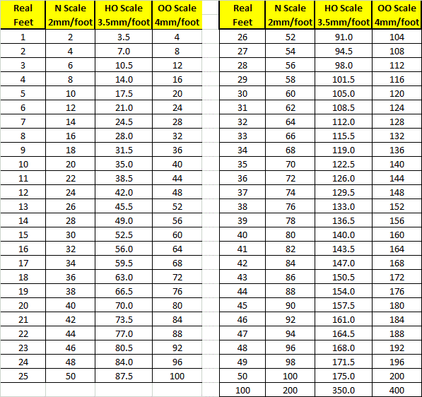
N/HO/OO Scale Conversion Chart.
A useful real feet to scale conversions in millimetres.
All items appearing on this or any page of this web site are the intellectual property and © copyright of Brian Lambert. Unless otherwise stated.
You MUST NOT make available by placing them in any public domain area or in printed format any copies of Text, Image, Drawing or Video shown on this web site.
No item as listed above should be used, copied, linked to or forwarded by any third party without firstly obtaining the written permission of the web site owner - Brian Lambert.
You may freely and for personal use only, copy or print any areas.
You may refer to this web sites page electronic address detail (URL) in any other media - printed or electronic. Any such referenced URL should commence.... https://www.brian-lambert.co.uk/
Brian Lambert accepts no responsibility for any item appearing on this or any other page of this web site.
All items are given in good faith.
By visiting this web site you agree to accept and abide by all the condition shown above.