www.brian-lambert.co.uk

Here you will find some useful information I have both gathered whilst undertaking various projects.
Where is the best place for my model railway? Anywhere really, so long as its dry and free of excessive dust. Never run a model train set (Sorry, Model Railway!) directly on a carpeted floor, all you will succeed in doing is introducing fluff and dust into the loco's gearing and electrical pickups, resulting in a failed loco shortly afterwards. Build a layout onto a firm baseboard and try and keep the board at least a metre or thirty-nine inches above the floor. Some will advocate even higher board heights, but I've found anything over one metre isn't practicable for younger viewers and even some of the older constructors will struggle to gain access to the rear area of a layout, once it reaches these heights. Where to do this is entirely up to each person building a layout - loft; garage; shed; spare room it matters not, so long as you build with the approval and consent of your partner or parent etc. I have even seen small layouts in lounges, but never construct something that will look totally out of place or cause domestic disharmony (You have been warned!).
Location. A home for the railway.
What are the Pros and Cons of each site....
Lofts - Ideal for being out of the way and can offer a large area to use. Extremes of temperature are a problem, but can be helped by a window or extractor fan in the summer. If you can afford it air conditioning will ensure a constant temperature and humidity level, but these units are expensive. Lack of height to walk around, especially in more modern buildings can be a problem and don't forget the water storage tanks may take up a lot of space. Never, ever, cut or alter any trusses or other roof timbers unless you really like having your roof in your lounge! Also consider the thickness (depth) of rafters or joists which will need to be sheeted to allow a flat and safe walking area. This area must support at least two adult persons weight and be covered in at least 20mm boarding or floorboards. Watch out for cables and pipes that run on top of or close to the top of joists when securing the flooring - also allow suitable access points for future building repairs and maintenance etc. Don't forget you will probably need both lighting and power supplies installed as often there is no mains power in a loft!
Garages - Much the same as for lofts, due to the extremes of temperature. Though probably not quite so hot in summer! Dust and insects (Spiders especially) will be a problem here. Sealing up the main cars access doors will help with the dust problems, assuming there is alternative access and the main doors are not required. Usually you will find only one course of brickwork between the internal and external of a garage i.e. there is no cavity. Though this shouldn't interfere too much with the modelling processes. But be aware that there may only be approx. 4 1/2" inches of brickwork between you and your neighbours garage internal walls face, so care is needed when drilling for fixings etc. Electricity in garages is normally not a problem as often both power and lighting are provided even if not, it's not a serious issue to get power into a garage. A nice level concrete floor will normally be found, but treat with caution as concrete floors are renown for producing excessive dust and making your feet uncomfortable. Consider a carpet or other floor covering for the main areas. Some form of heating will be needed for winter use.
Sheds - Similar to garages, but often located remotely from the main house. Nominally wooden in construction they provide little or no thermal insulation at all, so consider installing a suitable insulation material and internal cladding to the walls. Almost certainly there won't be any electrical supplies to a shed. This will need to be installed and the cost of supply, sockets and lighting will need to be included in the overall budget, which may become excessive? A word on mains electrics.... Always employ an "approved" electrical contractor to undertake your work unless your 101% sure of what your doing. In fact, part P of the building regulations, requires you to obtain a certificate of test for the installation - you normally won't be able to do this yourself! Shed size is another governing factor, if you can only accommodate an 8' x 6' shed and you plan to work in "00" gauge or larger you may find space is rather tight! Sheds should really be built on a solid base - patio slabs or similar are ideal these will ensure that over time the shed won't slowly sink into the ground due to all the weight being placed upon the flooring and walls. Insect invasion will almost certainly be the norm, so always de-spider/de-ant and remove cobwebs before a running session.
Spare Rooms - Probably one of the best locations for human comfort! Electricity will already be installed and often central heating too. No major issues with insect invasion and often pre carpeted. I would recommend a carpet protector though, perhaps some sort of PVC sheet or a nice clean plastic tarpaulin covering the best Wilton will ensure there are no accidental spills suddenly appearing as marks or stains onto the carpet. NOTE: There's no known remedy for removing spilt super glue from carpet tufts! Care should be exercised if you're securing the baseboards to the rooms walls. Check for buried cables and pipes in the walls before drilling - use a buried service locator device beforehand. Similarly to sheds, the allotted space may restrict your ideas. So, always plan your layout well before commencing any construction. It's far easier to alter a paper or PC drawing than change the timber baseboards installed in a room.
BASEBOARDS. The Foundations of the layout!
Failure to ensure the baseboard is built to a strong and sturdy structure will result in later issues with sagging or buckling of the boards and poor track alignment and general bad running. So ensure your baseboard(s) are like the foundations of your home. These after all support the house above as your baseboard should the layout
FRAMING...
Timber - Typically for many years model railway baseboards have been constructed from 44 x 21mm (2" x 1") PSE timber, the timber being placed on its narrow edge up (to the baseboard underside surface) and all being set out on a square grid pattern of ideally no greater than 400mm (15" inch) spacing . Larger sizes of timber can be used, but this does add extra weight. I wouldn't recommend using anything smaller than 44mm deep for the outer side framing. Outer framing can be slightly narrower but deeper e.g. 69 x 18mm (3" x 3/4") or any depth over 69mm (3" inches)
Pre drill three 15mm or 18mm diameter holes in the cross bracing before fixing them in place and drill the holes nearer to the bracing top edge and arrange so as one is in the middle and the others towards the middle of the remaining length between middle hole and the outer edge. These holes will later allow wiring to pass across the board unhindered.
See an example in the top image in the photos below.
Another method of construction, which is only really suitable for permanent layouts, is the ‘L’ girder system. I used for this on my former permanent layout, constructed in one half of my double garage. It is formed of either one solid length of 3” x 2” (69 x 44mm) timber or from perhaps easier to obtain 3” x 3/4 “ (69 x 18mm) PSE and 2” x ½” (44 x 12mm) PSE timbers being screwed and glued together. If you’re lucky and can readily access 3” x 2” timber, this then has a section cut out which is some 1” x 2” . The resultant timber piece left will be ‘L’ shaped. This cutting will require some serious woodworking machinery to undertake the process. i.e. a bench mounted circular saw. Much easier is to screw and glue two lengths of timber together to form the basic ‘L’ shape. This becomes extremely strong in the downward direction. ‘L’ beams can then be free standing and held by suitable legs or one ‘L’ screwed to the wall and the other supported on legs. Two parallel ‘L’ girders are the foundation of each span. It may seem strange that where screwed and glued timber has been used, I haven’t opted for the top rail being the same thickness as the horizontal rail? This is because I have discovered that ½” x 2” (12 x 44mm) is amply adequate and when the glue has dried the resulting ‘L’ is extremely strong – why use a thicker and more expensive timber? Once the two ‘L” girders are in place they are held parallel to each other with cross joists which often extend out beyond the ‘L’ girders. These in my case are from 2” x 1” (44 x 21mm) timbers screwed in place at 12” (300mm) intervals. It must be remembered that the joists are fixed without any glue – screwed up from underneath through the top ‘L’ baton.
See the three photos below which will show the basic idea.
Ply Wood - A nice material to work with, but I would recommend that for all baseboards the minimum depth be set to at least 70mm, much below this and there is a serious risk of long lengths starting to warp! Ply is also ideally suited to both flat topped (Sheeted) and 'open top' construction and allows reasonably sized boards to be built without being over heavy.
MDF – I experimented with Medium Density Fibreboard and used 9mm thick MDF cut to approximately 100mm depth and used these as an overall framing instead of the 44 x 21mm timber. It proved to be more than suitable and isn't so heavy to lift as a conventionally framed baseboards are (mine were all portable). However, I did pre drilled a series of 1” (25mm) holes into the internal sections which reduced its overall weight which also allows ease of wiring, additionally I sprayed every section of the MDF with a quick drying varnish to protect the frames from ingress of moisture. Also I braced every external corner with some PSE timber (21x44mm) cut to fit inside each right-angled joint to give really firm bracing at corners. Always either screw and glue using woodworking PVA or nail and glue all joints regardless of construction material. On portable layouts I wouldn’t recommend individual boards much over 2ft x 4ft (607 x 1220mm) as over this size the boards become heavy and difficult to handle.


BASEBOARD TOPS.
This is of your choice, but one of the best for ease of track laying is :-
Sundeala board - It is extremely easy to push track pins into it and it holds them in place afterwards. Often this is available via good model shops in pre-cut sheet size of 2' x 4' (607 x 1220mm) by 3/8" (9mm) thickness - which is convenient for carrying. This product will often warp or sag dramatically unless its adequately braced underneath. It is best laid on top of a firmer under board such as Plywood.
Ply - is another easy to use material that can be used. Be careful that this doesn’t warp or sag. So keep to a board of at least a minimum of 9mm thickness.
Soft Board - I would not recommend this material as this fails to hold track pins securely will warp and is of little use to the modeller.
MDF - needs very careful cutting as the dust can be harmful, it also suffers from possible moisture ingress unless it’s sealed completely and it’s really hard to drive pins into. Seal with varnish, paint or PVA glue etc to prevent moisture ingress.
Chipboard - 1/2" (12mm) is ok, but adds considerable weight to the construction and again is hard to drive pins into.
OSB - Oriented Strand Board. Normally around 11mm thick but can be found in various thicknesses. It cuts easily, its edges can easily be damaged its main disadvantage is its heavy . I'm experimenting with this material on my new layout. Click the link to be taken to the page High Hopes
Insulation - Sold in sheets of between 10mm and 100mm thickness sold under a UK trade name such as Kingspan. Light weight but will need bracing on thinner sizes. Can its quite hard for it to grip screws securely and great caution is needed with solvent glues etc.
All in all, I would go for a top made from suitable thickness Ply.
Portables - I also recommend that if a layout is to be portable you must always take into account the final weight and size of the construction. You should be able to lift one board unaided.
Fix the chosen board to the framing and cross bracing timbers by PVA woodworking glue and either screw (countersunk head screws) or pin it with suitable panel pins or oval nails driven in below surface.
LEGS
These must be at least a minimum of 2" X 1" (44 x 21mm) PSE and braced to prevent movement. As I stated earlier, I aim to have my layouts around 39" (1000mm) above floor level. Trestles are one option and these can be very easily made from some 44 x 21mm PSE and a couple of 50mm butts or two 30mm back flap hinges. The drawing below shows the simple format these take and the legs are prevented from opening too wide (and causing collapse) by a length of small linked chain spanning the two cross members, which also offers some means of height adjustment too. Notches have been cut into the cross members to allow the baseboard side rails to locate and prevent any sideways movement. Don't forget any additional internal baseboard strutting will also probably require a notch or notches cutting in the cross members too. Fixed layouts can use thicker timber for their legs such as 63 x 38mm CLS stud work timber.
Trestles work well on both semi portable and fully portable layouts. However, on on my former portable layout I opted for fixed 'Up & Under' hinged legs. To enable this I used 1¼" (30mm) back flap hinges to pivot legs up under the baseboards. There are cross braces fitted between the two uprights some 12" (300mm) above floor level as in the trestle construction. Then I use an angled brace which locks onto the legs cross brace and also locks onto one of the baseboards framing timbers underneath by using back flap hinge, this time with their pivot pins removed and a suitable replacement pin (Nail or split pin) used, once the brace is located in place. These angled braces are roughly at 45 degrees from the leg brace to the underside of the baseboard. This construction can be clearly seen in the photograph and drawing below.
Picture above shows the underside of a typical portable baseboard.
Note the simple single ended leg construction, the diagonal brace which secures leg in a locked open position.
When the baseboard is abutted to the next board the whole layout becomes more self supporting.
The first board of the layout has two sets of legs to enable it to be stood up on its own.
Where a layout is to be permanently fixed, then leg sizes need to be slightly larger at 2" x 2" (44 x 44mm) minimum. I would recommended that the front legs are always of at least this size, while the back can be either on similar legs or fitted onto batons screwed to the walls. Under layout storage is then possible by having some suitable shelving installed about 15" (400mm) above the flooring. Do leave room though for access to the underside of the boards for layout electrical wiring etc
On my permanent layout, utilising the ‘L’ girders, I have used 2 ¾” x 1 ½” (63 x 38mm) CLS timber to make the legs. This is readily available from most DIY stores – Wickes, B & Q etc in the UK and has nicely pre rounded edges too! These legs once cut to length, were screwed and glued to the main bracing timber or ‘L’ girders at the corners and roughly at half way along the two longest lengths around an equal spacing and of not greater spacing then seven feet apart.
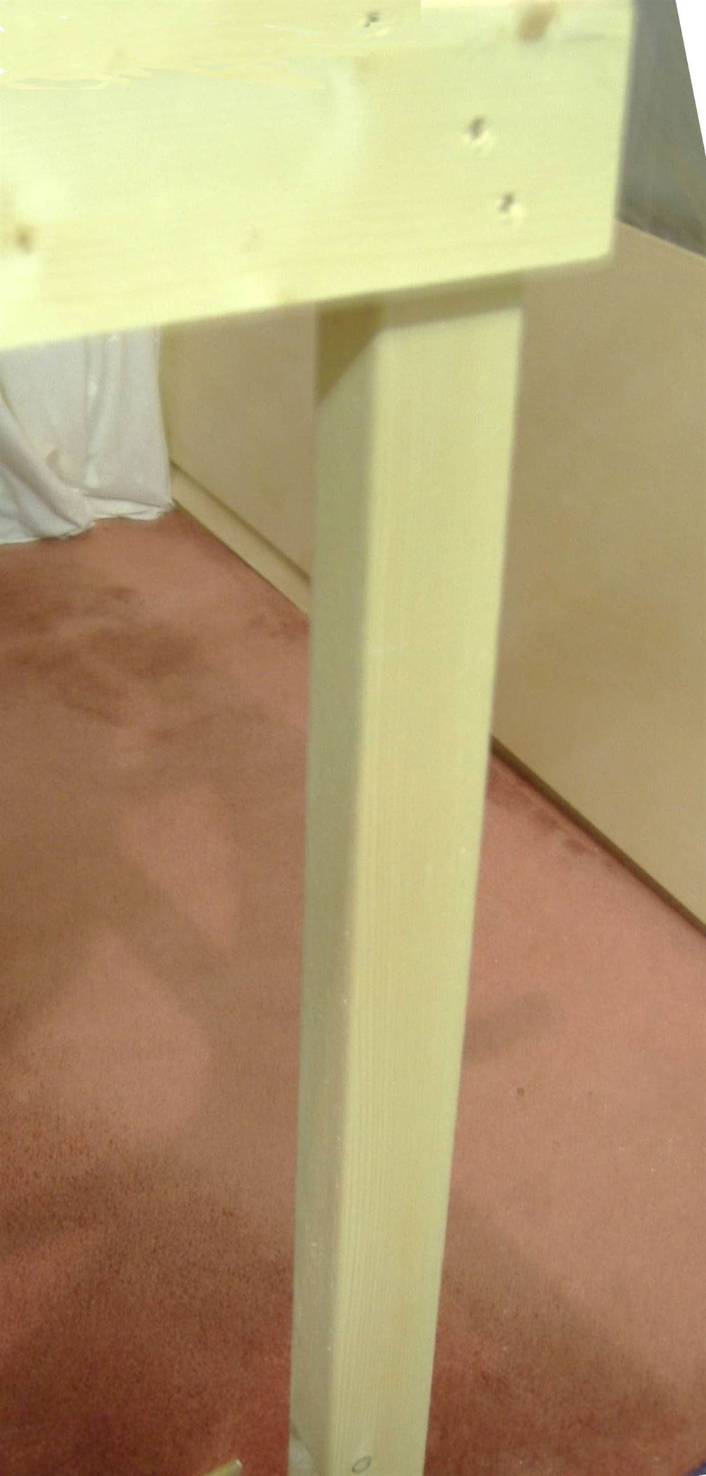
In the picture above a fixed layout leg is shown.
This is made from 63mm x 38mm CLS (Stud work) timber and has been screwed and glued to the top rail, which in this case is actually a corner joint.
Layout Height
The floor to baseboard top height is a very personal thing. The main thing to remember is that the builder and layout operator need to be comfortable with the final height. Too low and back ache sets in quickly and too high younger views may not be able to see the trains running! Many layouts are built to a nominal above floor height of 1000mm (39 inches). If you are building a multilevel layout then I would recommend the lowest level board top be set to 1000mm and that becomes the datum for builds above (or below at times!) See Link to High Hopes layout
Whatever height is chosen, always ensure you allow access to rear areas. The recommended maximum reach across a layout front edge to the furthest reachable area is no more than 900mm (3 feet) anything over this raises the risk of accidental damage occurring to any scenic items near the front edge.
All items appearing on this or any page of this web site are the intellectual property and © copyright of Brian Lambert. Unless otherwise stated.
You MUST NOT make available by placing them in any public domain area or in printed format any copies of Text, Image, Drawing or Video shown on this web site.
No item as listed above should be used, copied, linked to or forwarded by any third party without firstly obtaining the written permission of the web site owner - Brian Lambert.
You may freely and for personal use only, copy or print any areas.
You may refer to this web sites page electronic address detail (URL) in any other media - printed or electronic. Any such referenced URL should commence.... https://www.brian-lambert.co.uk/
Brian Lambert accepts no responsibility for any item appearing on this or any other page of this web site.
All items are given in good faith.