www.brian-lambert.co.uk

High Hopes
This page will be updated as work progresses.
Please call back to check progress.
Warning: Photo Intensive page.
Allow time to load fully.
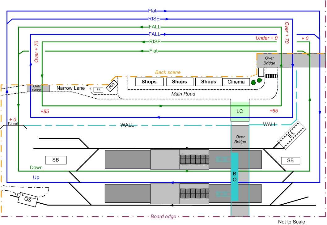
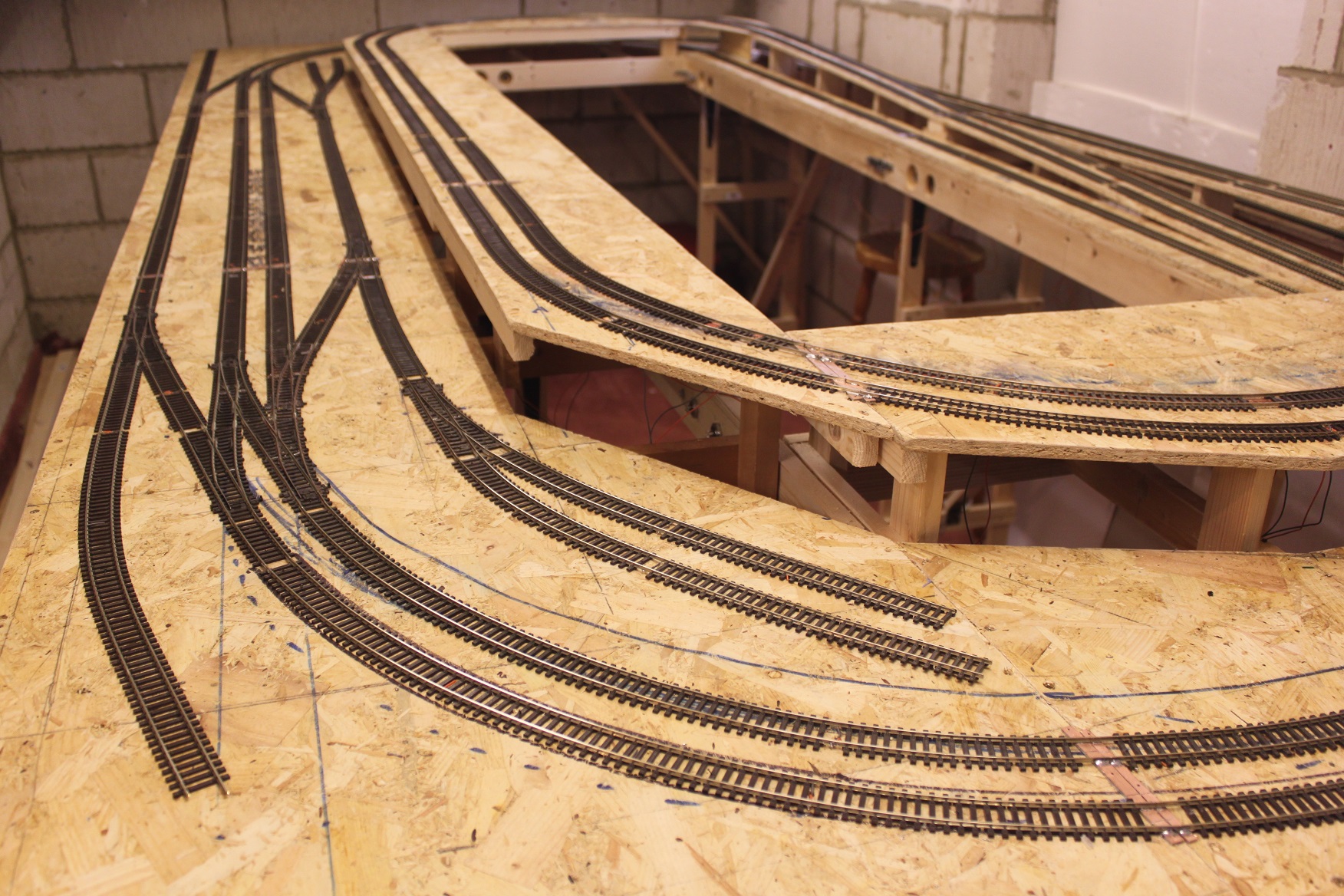
Basic Baseboard and Track plan.
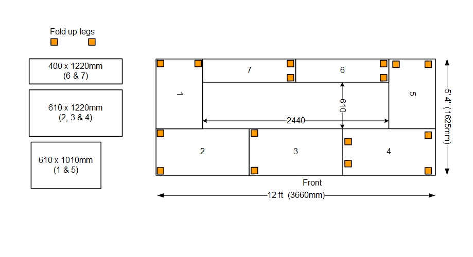
The first steps was to obtain suitable timber (Planed Square Edge - PSE) and sheet boarding for the tops. For this project I am trying 11mm thick OSB3 board (Orientated Strand Board). Underside outer framing will be of 69mm x 18mm PSE and cross bracing at 300mm intervals made of 44mm x 21mm PSE. These will before fitting, have three 15mm dia. holes drilled in them nearer to their top edges. These holes will allow for later wiring runs. The deeper outer framing will help protect the point motors and other underside electronic items and give good rigity and strength, while the smaller cross bracing timbers, when installed narrow edge to baseboard, give strength to the top but reduce overall weight. Fold up self contained legs will be added too.
The first frames and tops are constructed
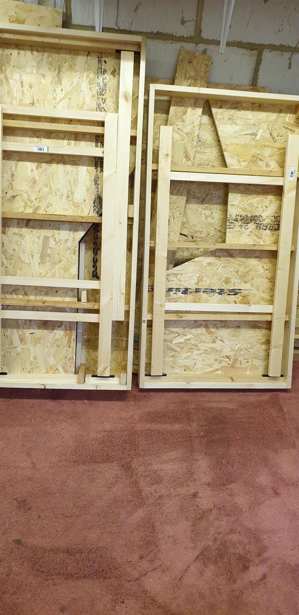

Fold up legs are constructed from 44mm x 21mm PSE and braced apart by two horizontal timber braces which are screwed and glued to the legs. Each leg has an adjustable foot and 200mm Tee hinges are used to act as the pivots. Each leg is braced in the open position by a diagonal timber strut with Back Flap hinges at each end. See details below
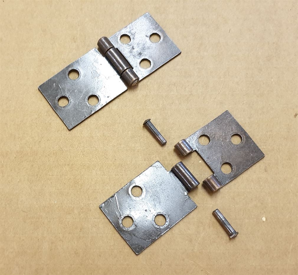
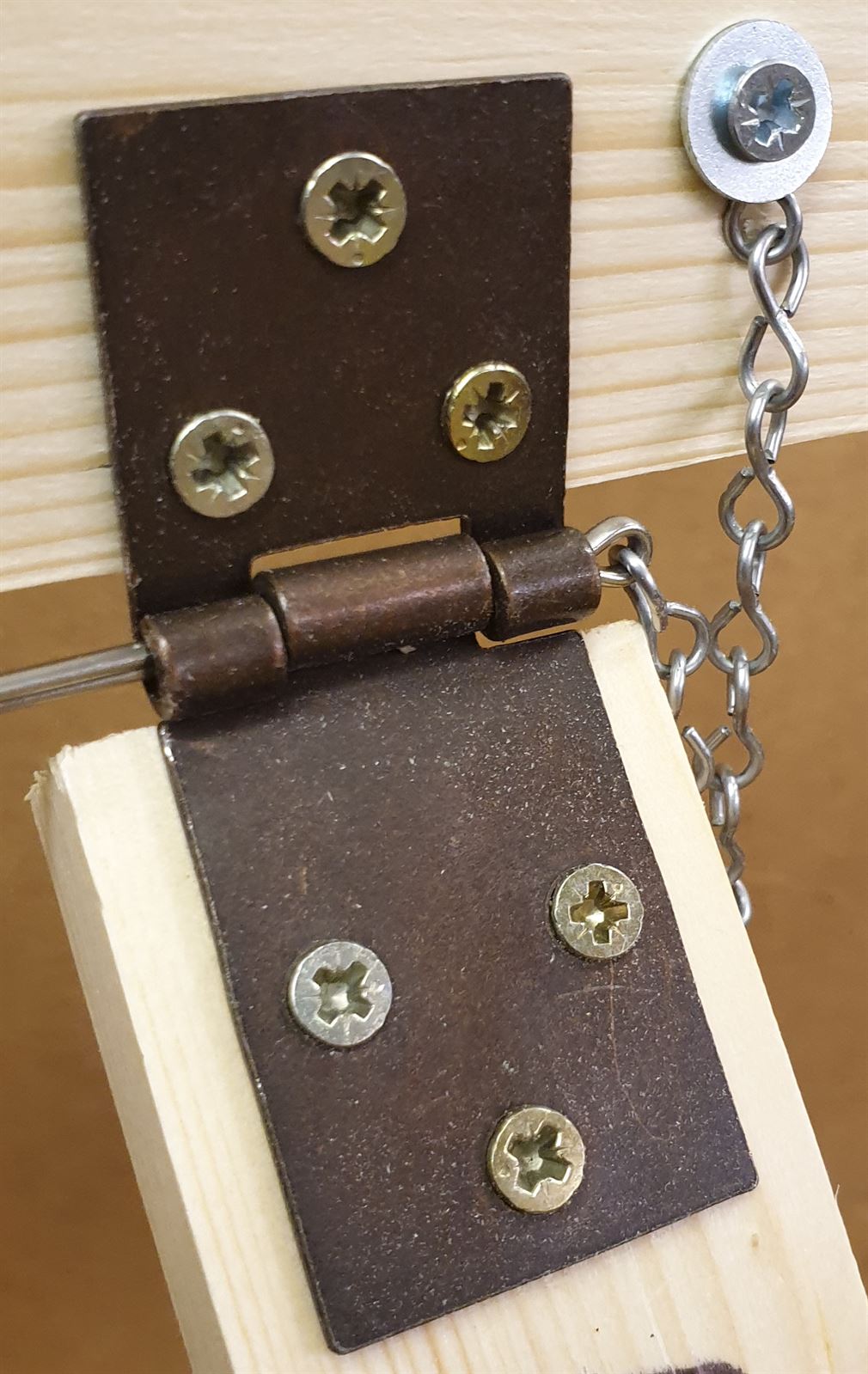
To allow the fold up legs to be stored within the framing of each baseboard yet still allow the leg to be firmly locked in the down position 32mm Back Flap hinges are used at both ends of the strut. Each hinge has its original pivot pin removed and discarded and a split pin on a short length of chain is used to retain the struts firmly and securely. These make folding up the legs very quick and simple.
I have so far constructed five of the seven baseboards - Nos 3, 4, 5, 6 & 7 are ready for a coat of varnish or dilute PVA to seal them and then once dry I need to make room for the last two boards in the garage by moving them all forwards.
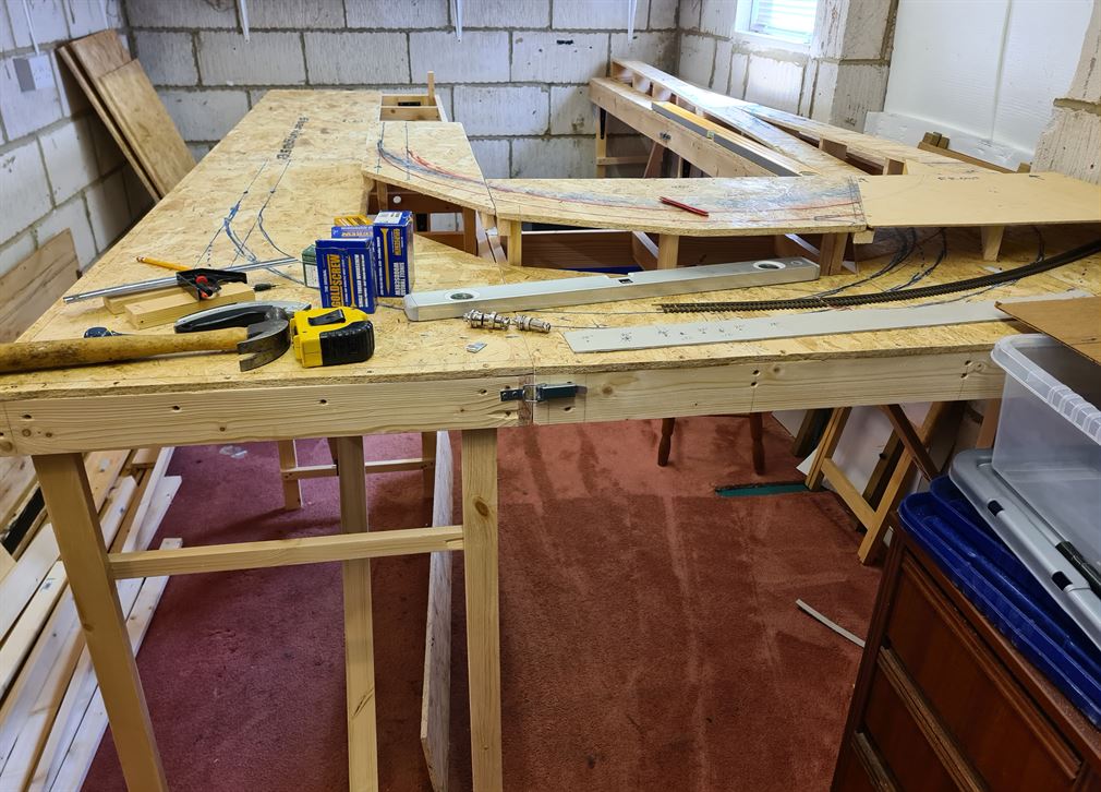
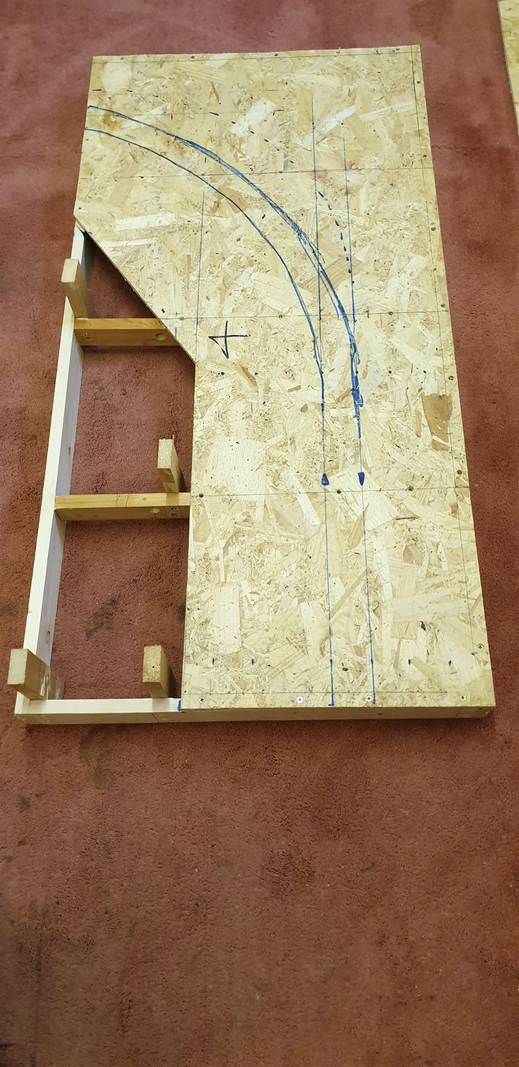
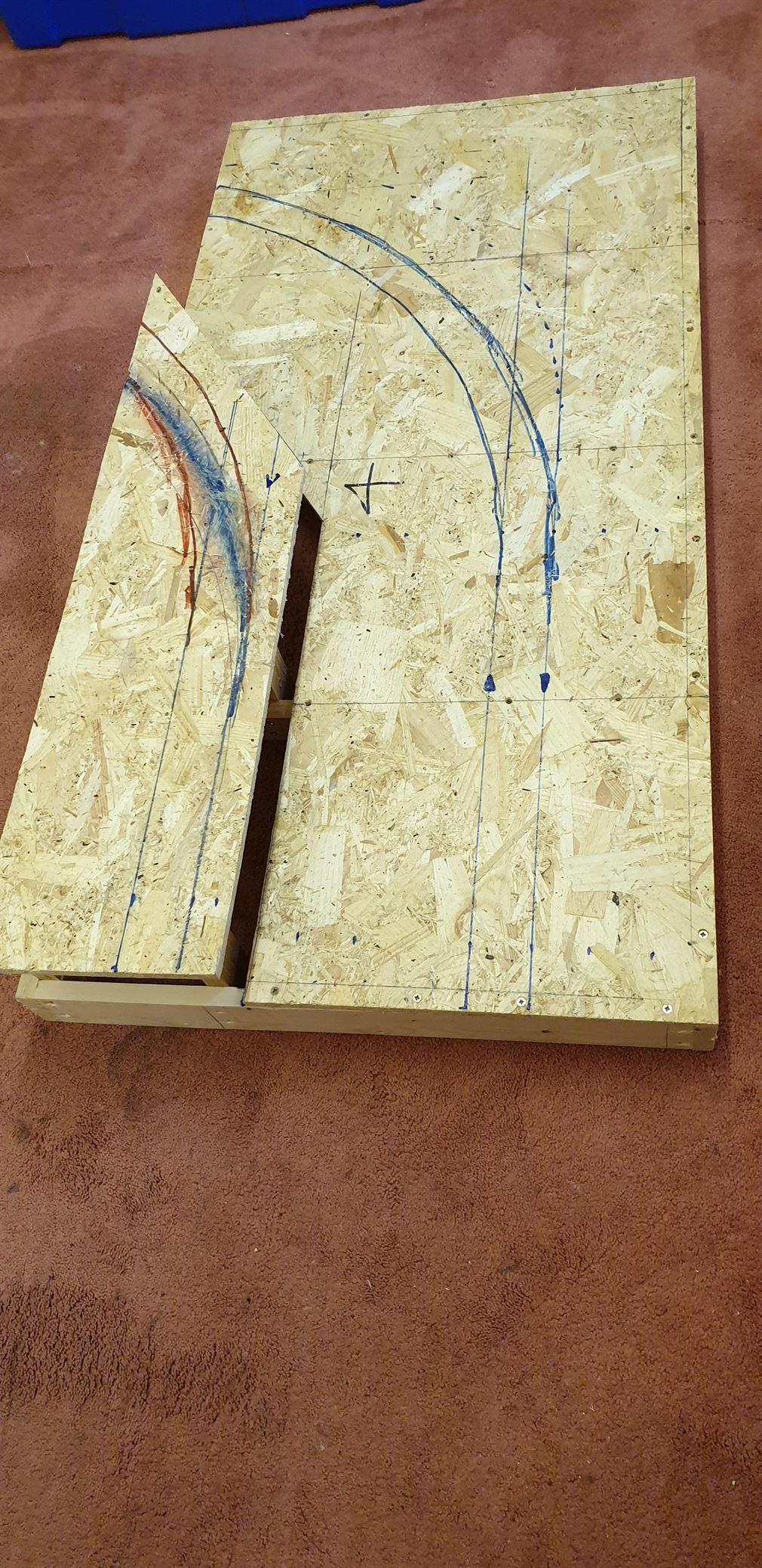
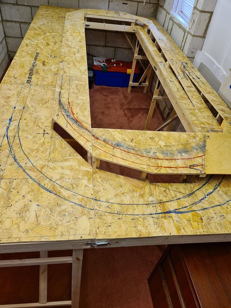
Baseboard top for board number 2 cut to allow for the upper level/raised section and the turn towards board 1. Next is to make the framing. But that will have to wait for a day or so now!
All seven baseboards have now been constructed and assembled to form the layouts rectangular shape. All surfaces have been sanded and then given a coat of dilute PVA adhesive to act as a general sealant. Next track laying commences!

Next item to be tackled was the electrical connections baseboard to baseboard. For this I have opted for two different sized 'Aviation' plugs and sockets in four way pin/socket per connector. I have chosen 16mm and 20mm diameter connectors, the larger being used for the DCC pair of feeds and 12volt DC power for all the electronic boards and Servo motor drives, while the smaller is used for CBUS data lines and two spare pins. By using two of differing sizes there is no chance of accidental cross connection occurring. The Aviation sockets have a threaded protrusion on their front onto which the plugs securing ring locks the plug tightly onto the socket. The problem being if these sockets are mounted onto the front surface of the support framing timbers they extend out beyond the front edge and are then likely to be knocked or damaged during any later transportation of the layout. So I decided to drill two holes for each socket and also allow finger room too for tightening and removal of the plugs. A hole of 32mm diameter was drilled for the 16mm socket while the 20mm socket has a 45mm diameter hole. The sockets were mounted onto 6mm thick ply and that is bolted to the rear of the bracing timbers.
.


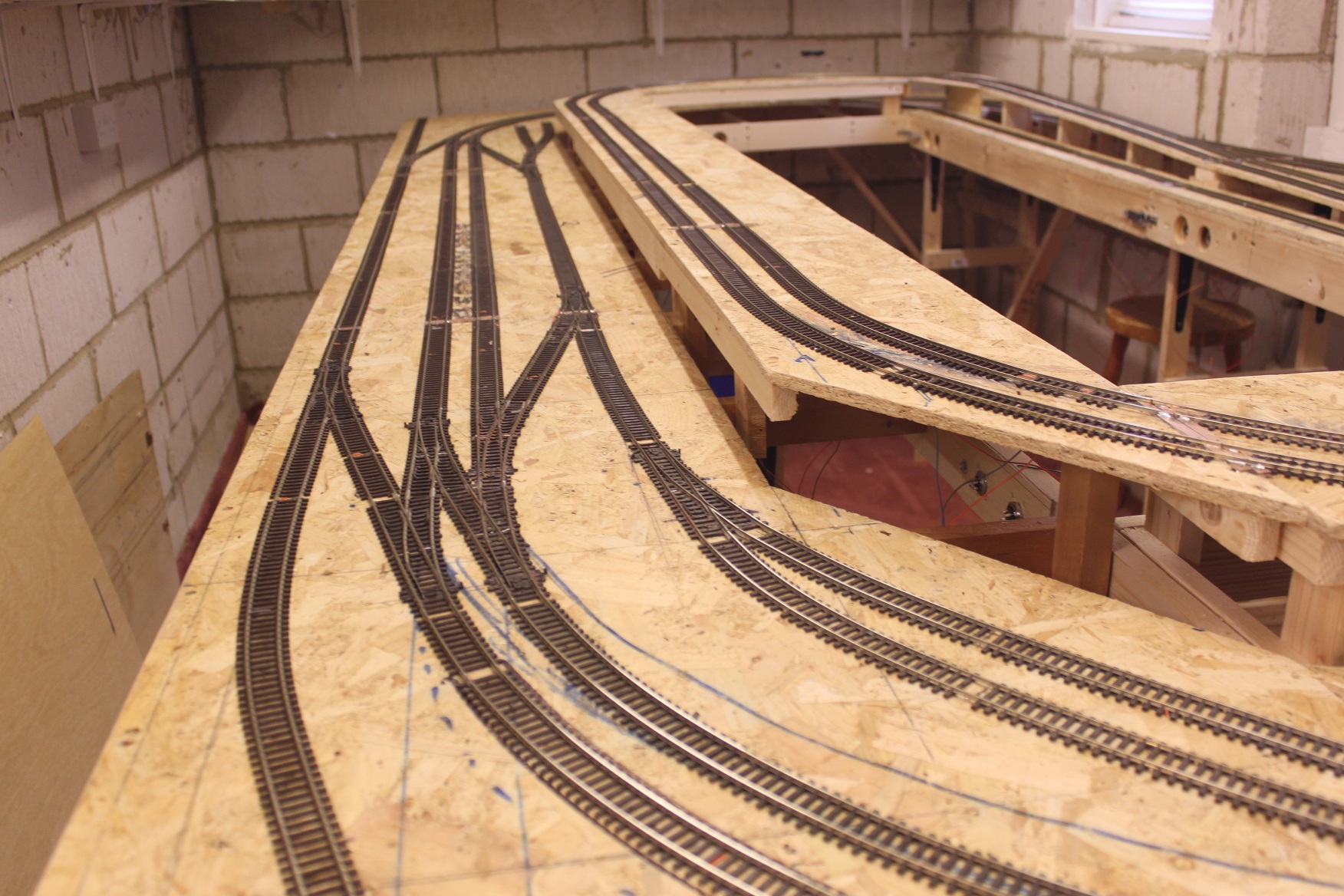
Now commences the track laying! I have a lot of Peco Streamline code 100 points taken up from the former 'Elmswood' layout and some sections of flexible track too, plus a new box of 25 lengths of SL-100 track. So this has to the choice, as it would be wasteful to go over to Code 75 profile track. In fact I've not had any issues with Code 100 looking too large, especially once its rail sides are painted rusty colour and the track ballasted.
Please remember you can click on an image to view it larger.
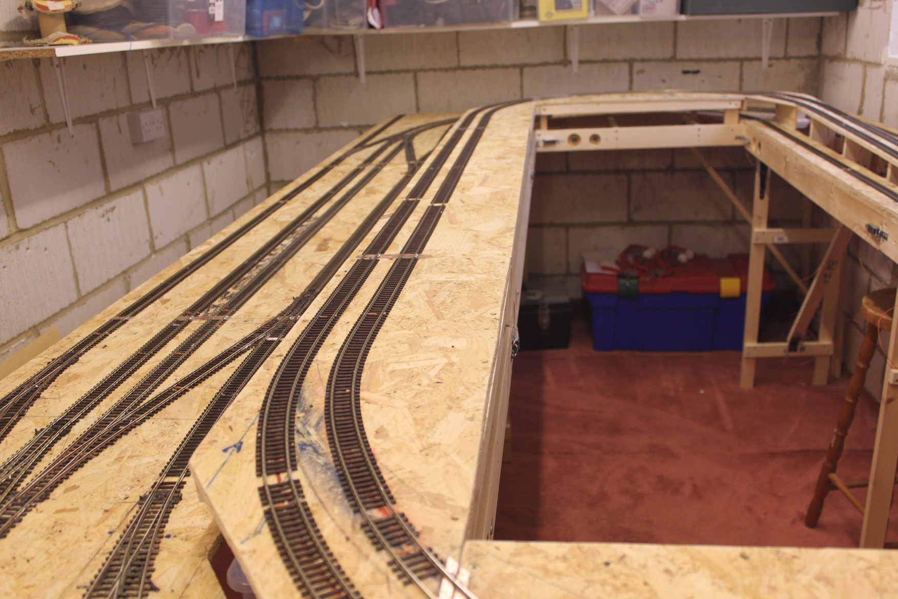
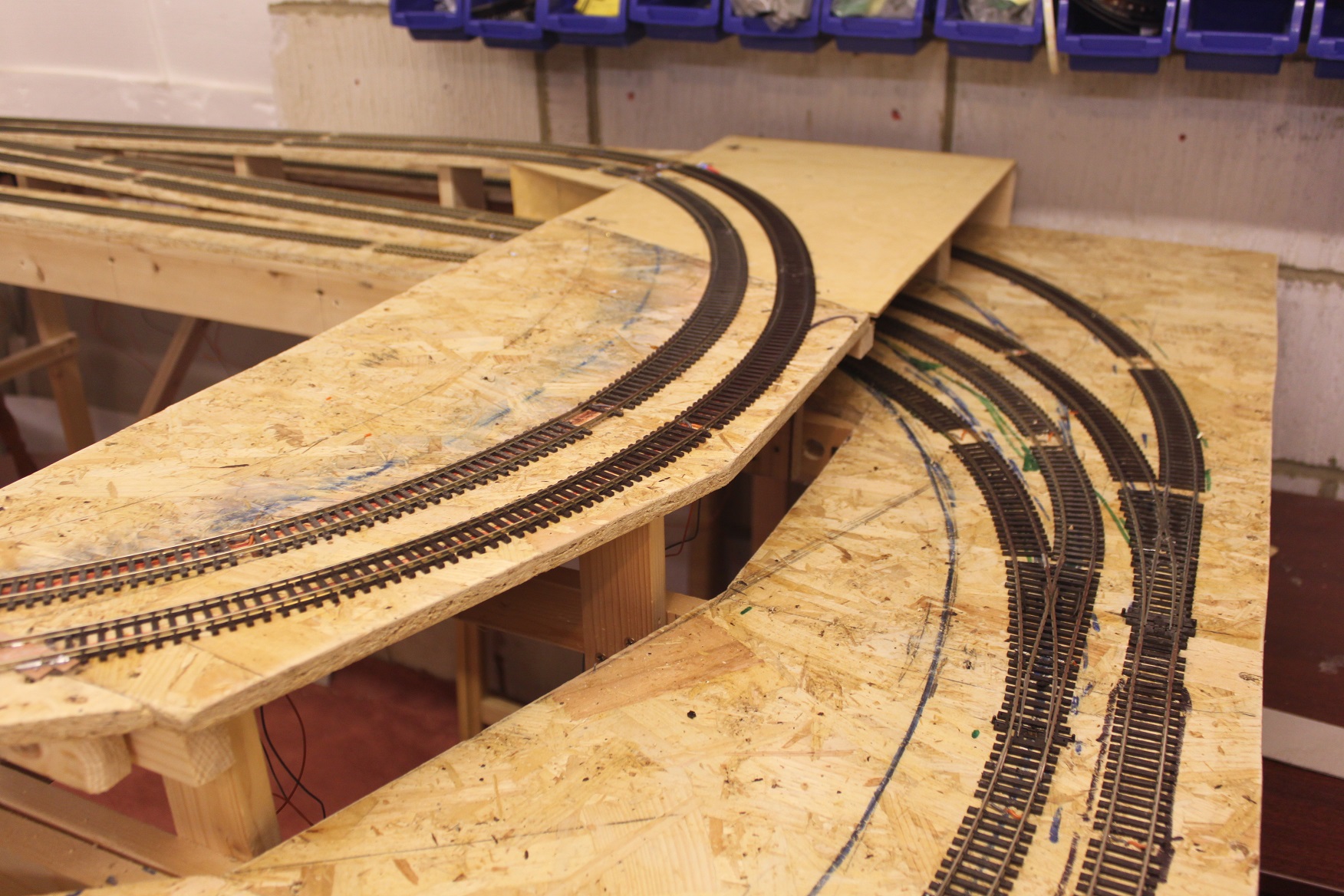
Track laying is a slowly coming together and I'm now around 75% completed. I have today run out of 1.6mm thick Copperclad board which once cut into approximately 4mm wide strips is used for retaining the rails at baseboard joints. More is on order but I.m now at the mercy of the postal system! Track laying is slow as each piece of track has to have a pair of dropper wires soldered to the rails undersides before laying that section. Gaps in sleeper spacing will be made good before ballasting.
I have at long last completed 99.9% of all the track laying! Only ends of sidings to sort once buildings are purchased - Engine shed, Goods shed etc.

So onto the installation of the under baseboard wiring!.....


Wiring of the baseboard commenced. As I'm using a CBus network around the layout for all points, signal and indications, only a twisted pair of wires are needed for this, with all CBus modules tapping off this pair of wires. In addition a 12 volt DC power supply is needed for all the modules, Servos and anything else that may need to be powered later on (e.g. Colour light signals, Building and Street lighting possibly?). Plus of course the DCC pair of Bus wires. I have additionally allowed a spare pair of connections across each baseboard joint for anything else later on. Wires are: DCC Bus pair 32/0.2mm in Orange and Grey. 12 volt DC power in 24/0.2mm in Red and Black. CBus Data pair twisted of 7/0.2mm in Yellow and Blue and finally the unused for later possible use are a pair of wires in 16/0.2mm in Green and Brown. I have opted to use 'Aviation' connectors as shown above, and they are in a 2 by 4 way pin/socket arrangement and these can be seen now wired in the pictures below. Note the DCC and 12 volt DC plug and socket are larger than the data and spare pair connector is, this is to prevent accidental cross connection occurring.


Below shows the simple means of connecting all the Dropper wires from the rails above onto the DCC Bus pair of wires uses two loops of copper wires stripped from main cable and inserted into one side of a four way terminal block. The bus 'in' and 'out' wires connecting to the opposite side on the block. Then all the droppers are soldered to the two copper wires.

All my points are to be operated by Servo motors and a single micro switch operated by the Servo's arm flips the Electrofrog points frog rails polarity. These are shown below.


In the two images above and fitted on the right hand side of the Servo mounting bracket can be seen the small Micro switch. As the servos arm moves over from the current left position to the righhand side it compresses the micro switches lever which causes the internal contact inside the micro switch to change-over and in turn flip the electrofrog points polarity.


After weeks of baseboard building then making up electronic control kits and wiring it all I was at long last able to power up the DCC system and place a couple of locos on the tracks and let them run the complete circuit of tracks in both directions. One baseboard track joint was found to be slightly out of line and a quick heating up of the copper clad sleepers soldered rail joint soon had the rail back in place. The first two locos, one with a couple of carriages behind it, can be seen above.


Control panel built and tested. Panel facia is a professionally printed 3mm thick aluminium photograph. This was carefully drilled for push buttons, LEDs, lighting selection rotary switches and the DCC RJ45 connection for the handset plus a panel meter for 12 volt power monitoring. Inside are MERG CBus modules made from their kits and these allow two wire operation of all the CBus modules that are dotted around the layout - Point operation, track occupancy indications on four sections of hidden sidings and lighting etc. Plus a special Panel CBus module providing the push button and panel LED indication connections. On the left hand side of the frame (out of view) are the sockets for onward cables going to the layout, including 2 x CBus twisted pair wires, 2 x 12 volt power supplies. 2 x DCC rail feeds and a USB socket for computer connection to the CBus modules for setting up their operations.
Scenic progress has been slow and not helped by the cold temperatures of January and February in the garage/railway room, plus the Covid lockdown making purchasing anything a chore, as all none essential shops remain closed and the internet is the only way to obtain items. But I have made a start on the Booking office/station entrance which will sit on a over track bridge and a set of stairs that will lead down to the two island platforms. The problem is the bridge and booking office are on one baseboard while the covered walkway and stairs are on an abutting board, so the two can be separated for transportation at any time. Hopefully the join will be covered by the replica lead flashing I've applied to the rear of the walkways roof and that should lightly press onto the rear wall of the booking office and hide the join! The Booking office is a LCut Laser kit turned 180 degrees around so as what was meant to be the platform side has become the entrance and the now rear wall is a flat surface which had windows in it, these are covered over by a modified Scalescenes footbridge card kit. The span across all tracks and supports for the bridge decking etc has three H girders each 16mm deep This in OO equates to areal depth of four feet, so I feel a long span can be justified! When completed the bridges roadway will lead to a gated level crossing over the upper levels two lines and then into the town at the rear of the baseboards.


The two island platforms are next. Here I have opted to use 15mm x 25mm plastic cable trunking as the main supports, mainly as it is far cheaper than timber and it is exactly the right height above baseboard, so as when the platform top is fixed and produced from 2mm card it is the correct height above rail top. The cable trunking offers dead flat and smooth sides and also I've used the Self Adhesive variety. The track facing sides are covered in brick paper and the card tops glued to the edges of the trunking with UHU adhesive. The card surface is then covered in cut pieces of Scalescenes platform surface paper, which I've chosen to be the slab variety.
Click on an image to view it larger.


Once the two platforms are completed the next job will be to run in the LED lighting feed wires, so as they are hidden from view. The Booking office has three LEDs and the stairs also have three LED lights.
Over the last few days my time has been involved in constructing a Scalescene Island platform building (one of two needed) plus a 1070mm long arched retaining wall for the area behind the platforms, where the high level tracks are located. Additionally, the LED lighting for the Booking office and stairways leading down to the platforms have all been connected up and tested.


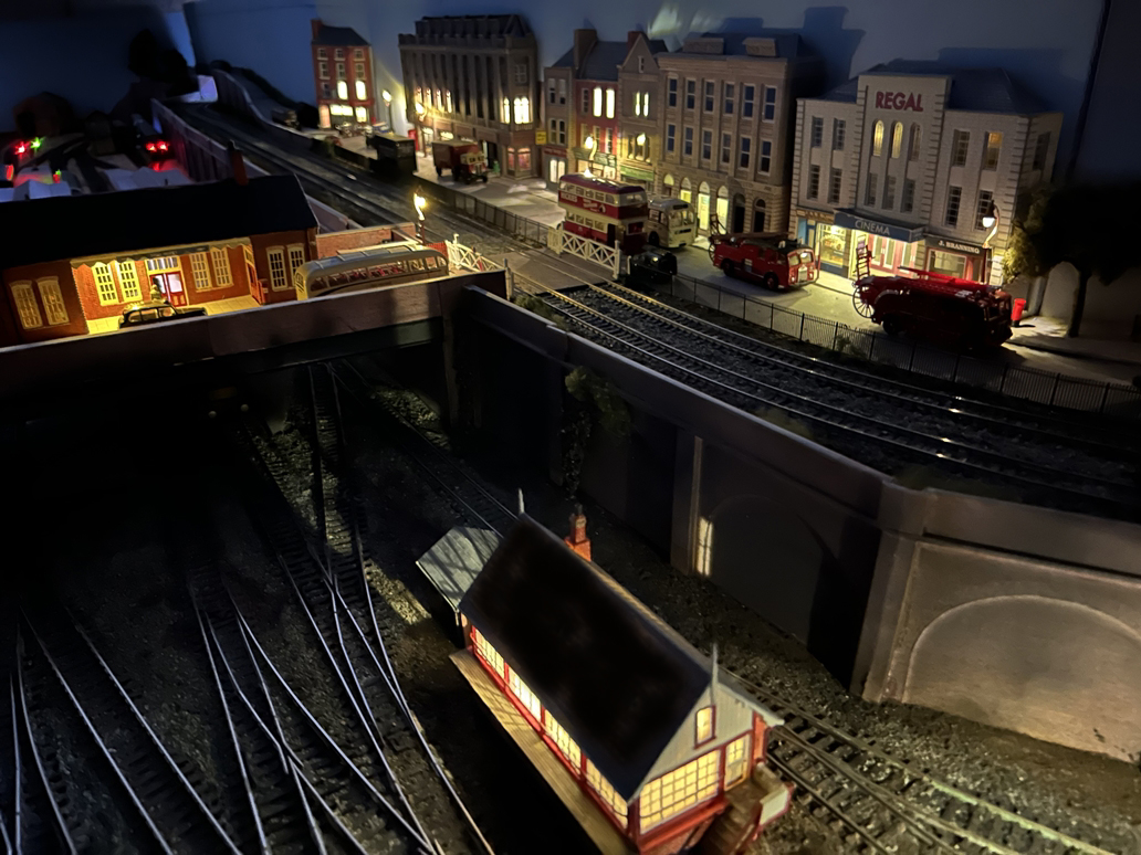
The last couple or so weeks I've been purchasing then building Metcalfe low relief shops and adding a 100mm wide additional baseboard to the read of the front upper level. This will allow a roadway of deeper dimensions than originally planned to be installed, in front of the shops and towards the upper level tracks along the front of the layout. I have also constructed a second Island platform building. All buildings have a limited number of LED internal lights added and four LEDs added under the canopy of each platform building. All these will be wired to the appropriate adjustable power source - Buildings. Station or Street light controls to allow differing sections to be switched On/Off or a section to be dimmed. All the Metcalfe buildings have had to be sourced on line and not all were available from the same supplier, so a lot of internet searching and checking of delivery costs was undertaken - they vary considerably! All this ordering, waiting for delivery and then building has taken longer than I anticipated. So a small delay is inevitable!
While waiting for other Metcalfe kits to arrive, I have been constructing a road bridge that will span front to rear on the right hand end of the layout. The bridge will make a 'scenic break' to the rear tracks, all of which are to be off scene. The long road bridge is made of card supporting pillars covered in brick paper and plate girder sides by Peco, two sections spanning the tracks and the third across the roadway which will pass underneath at the rear. The roadway will be 2mm thick card covered in tarmac printed paper.


Further work on the over bridge has been undertaken, with the girder bridge sides painted a dark grey and the four piers positioned and a road surface produced from card and covered with Scalescenes Tarmac Road surface paper suck to it. As the bridge is around two feet long, I printed the tarmac paper on A3 paper and that resulted in just one join being required. A pavement along the left hand side was printed and bonded to 1.0mm thick card, as too was the right hand sides kerb only section. Both were glued to the road surface. No sooner was the pavements down, road traffic appeared! The road itself is 80mm wide which is roughly equal to 20 feet in real size and the pavement is 25mm wide (6 feet).


Please remember you can click on an image to view it larger.
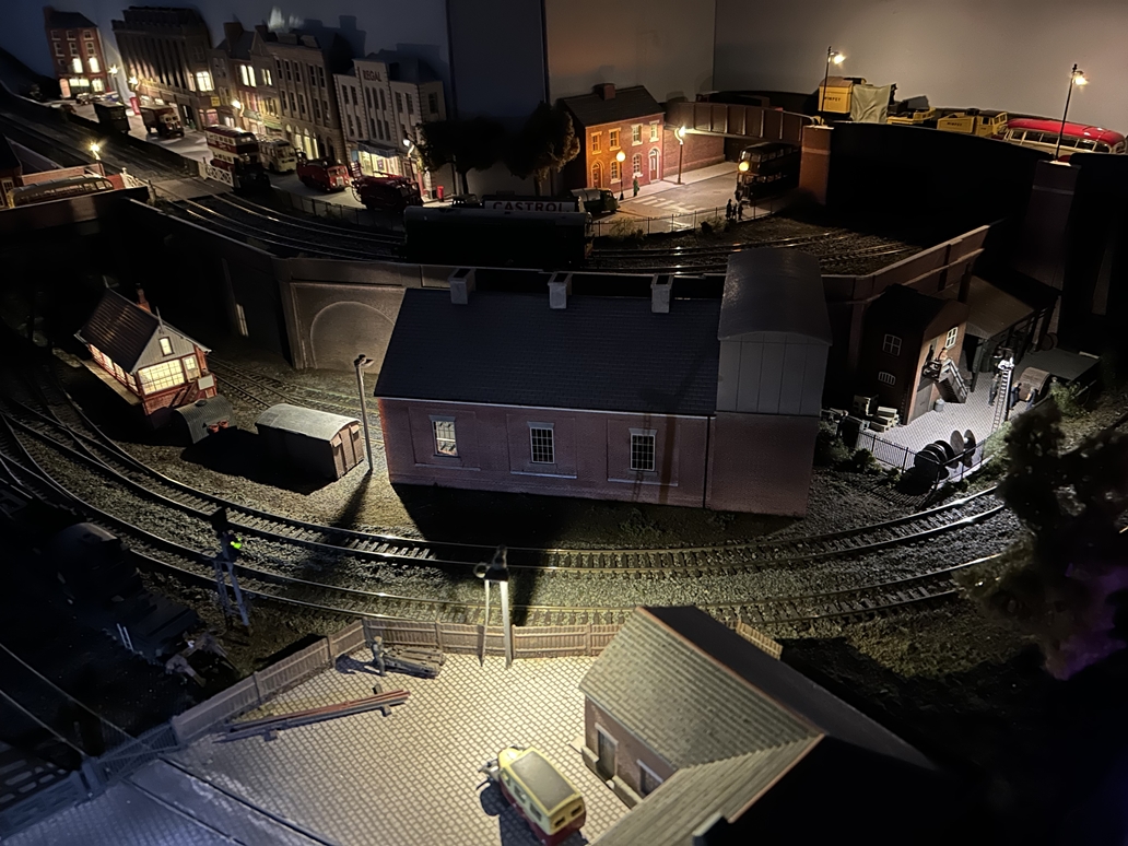
More Metcalfe kits are on order and pending their arrival, I have completed the arched retaining wall to the right of the station that leads around to the large over bridge. A Bachmann Scalescene engine shed has been procured and placed in position. This leaves a space between the end of the engine shed and the tall pier of the over bridge. This I hope to make into a railway S & T (Signal & Telegraph) depot of some sorts. A Permanent Way depot is to be constructed on the opposite side of the main lines to that of the engine shed.


While waiting for the arrival of a suitable building for the S &T Depot, I have laid the cobble stone paving and Tarmac entrance form under the over bridge. A fence and gate to the depot has been added. I've used Spear top fencing, but it is breaking badly along the tops, so it may get replaced or modified once the post glue has set over night?
The S&T depot building and Canopy arrived today, so have been temporarily positioned in the depot yard.


Three rear backboards cut to size from 6mm MDF sheets. These have now received two coats of sky blue emulsion paint. While the paint is drying, detailing work in the S & T Depot was undertaken. Still plenty more to do though! More work on the street scene above the S & T Depot and working Belisha Beacons installed at the zebra crossing and just the Traffic lights to paint and install on the narrow corner by the Co-op store. These will be worked from a home made electronic controller board with the lights changing every few seconds. Everything takes longer as all items are ordered on line and some deliveries are quicker than others.


Work has started on a Permanent Way Depot (PWay Depot) this is located across the main line from the S & T Depot and Engine shed. A couple of buildings have been temporarily placed to test their final position.


Work today has been slow. Fencing applied around the depot perimeter and gates are on order, but they are not expected to arrive until late next week. Two LED lit lamp posts installed and buildings glued down. A road into the depot fabricated and laid.
The last of the depot fencing added and two gates installed, one for rail traffic and the other road vehicles. Two Half sets and a Crossing are laid on sleepers pending their use when a line block possesion is granted or for emergency use. Next to tackle is the scenery around the depot perimeter.


Today has mainly centred around the tracks passing by the PWay depot, the engine Shed and the PWay depot approach tracks and the upper level track ballasting to the level crossing. Those who are sharp eyed will note that a new point and siding has been installed adjacent to the depots siding track. This allows the stabelling of the Breakdown Crane.


The High Street is taking shape with most of the low relief buildings in place and lights installed inside many of them. The track ballast glue dried overnight upto the level crossing and both sides of the main lines have been scenically enhanced with various scatters.
The engine shed will be the next area to tackle


Detailing work has been carried out from the main station over bridge around to the S & T depot, with a signal box added. A Colour light signal and the Breakdown crane has arrived into its dedicated siding. Other smaller details have been inserted, plus a flood light outside the engine shed. All the tracks have all been ballasted up to the platform ramp ends and various ground cover scatters applied. This all but finishes the North end of the layout with just street lights to install and connect up.


The main station area is now my next area for attention. The track under the booking hall bridge and through the platforms is ballasted and scenic scatters added to help make the ballast and Cess edges look more real. Two three aspect colour light signals have been wired and are automatically operated by electronic signal control boards and Infra Red train detectors As a train leaves the station and passes over the IR detector, the signal reverts to a red aspect and a timer starts, after time period which is adjustable and is currently set for ten seconds, the signal clears to a yellow aspect then after a further seven seconds it reverts to green These two signals are also controlled by the point position ahead, so one is always at red while the other shows a proceed aspect when the point is set for that route.


The last few days I have been constructing more signal aspect control modules and Infra Red detectors, mainly from MERG kits plus a couple of home built timers to delay aspect changes. With these all built and tested, I ordered an Eckon twin head three aspect signal kit and with the help of Online Models who manufacturer Eckon signal kits they were able to provide me with a shorter tube for the signal post, as it is platform mounted. The kit was constructed and all signalhead wiring extended via soldered joints and heat shrunk tubing covering the joints. The position of the signal was marked on the platform surface and a 5mm dia. hole was drilled through the platform surface and also through the baseboard. Then all the aspect feed wires were carefully threaded down via the hole and out to underside the layout. These were connected to the two aspect control boards. Power applied and they work correctly. This is really the very first part of scenic detailing to happen from roughly the middle of the two platforms out towards the Up side Southern end of the layout.

I have turned my main attention to the left hand end of the layout, which I call the "Southern end", I have now installed the backboards to the whole front of the layout and painted them Sky Blue to match the first boards installed, these form an L shape to encompass the rear and end of the front baseboards, In one place a short angled 'instep' has been created to bring the rest of the backboards back into line with the main rear longitudinal side frames of the front baseboards. This instep forms the area where the main high street road, that runs along the middle of the upper section, leaves the layout via a right turn corner in the road and heads out towards the villages of Much Hope and then Little Doing before it joins the Great North A1 road. A public house is situated in the angle of the instep and a narrow country road leaves the main road at that same corner. The country road climes a fairly steep hill to where it crosses over the upper level railway lines and then heads onwards towards open farm land above the lower level tunnel. A plate girder bridge spans the upper tracks and supports the country road.


The tunnel portal has been produced from a Scalescene's download and lined internally. Clearances checked for the tunnel sides against the longest carriage and loco, then the portal was glued in place. Surrounding walls added and next will be the framing for the ground cover.


More retaining walls have been produced from card and brick paper and then glued into their final positions. Then once their fixing glue was set, a lattice of card strips was Hot Melt glued in place to form a light weight but strong frame for the Plaster bandage, which is the next thing to be worked on. All card and brick papers have received at least three coats of spray matt varnish.


This afternoon my attention was turned to getting plastered! Well plaster bandage application to be more precise! Lengths of plaster bandage were cut onto small strips for around 25mm x 100mm or 25mm x 50mm and soaked in a water bath for a second or three, then laid in place on the previously made card strip framing. Once dry in around 24-48 hours, the plaster will become solid and can then be painted an brown earth colour (Burnt Umber is ideal) and then static grass and other scenic flocks applied. In the meantime the area looks like a disaster zone, but it should clean up correctly once the bandage has dried fully.
Click on an image to view it larger.

The last few days have seen quite slow progress, mainly due to the time the plaster bandage took to cure hard and family visiting. But once the plaster had dried I was able to give the whole area a coating of acrylic Burnt Umber paint. After a further 24 plus hours the area was sprayed with a matt varnish and once that had dried it was coated in neat PVA glue, while the glue was still wet various static grass effects were applied and a fence glued in place along the road side. A hedge on the scenic backboard side of the country lane was added. Three ready made trees planted and some whispy brambles and nettle effect added in some places.
This about completes this area, next will be track ballasting and scenic work on both the upper levels and lower level into the tunnel.

Over the last couple of months layout progress has all but been stalled! I did manage to ballast and scenically treat the upper left hand level and obtain a narrow signal box for the main line and some1950's style road signs and a finger style sign post. None of which have currently finally been fitted! Two platform canopy extensions have been built and canopy support columns made from two interlocking sizes of plastic tubing. One support column on each platfom carries the wiring internally from below baseboard up into the canopy roof for the LED lighting. Two Dapol newspaper kiosk kits have been built and painted and fixed in place, one on each platform under the new canopy extensions.


Mid March 2022 and the layout has gone! Not for good though, but due to forthcoming extension building works to the house, the garage home for High Hopes had to be cleared. So for the time being the layout is crated and stored under covers away from the building works.
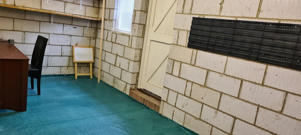
It is now mid August 2023 and after around 18 months in storage High Hopes has returned to its former place in half of a double garage. The wooden access door in the middle of the garages external wall has gone and is now solid block work internally with matching brick externally, giving a much better internal wall. However, while in store the layout has suffered damage to some of the scenic sections, including the large over track road bridge and the town back sceen. All will need to be corrected over the coming months, once electrical operation have been checked. The damaged bridge can be seen in these pictures below and the town scene is temporarily laid at the rear until work can be carried out to refix it in place.


Repairs have been made to the backscene boards. Road surface, fencing plus the removal of the corner shop allowing the roadway at the corner to be widened. Traffic replaced and the at least two lamppost still to be replaced once ordered and a couple of trees to purchase. But the layout is slowly returning to life.


Click on an image to enlarge it
With the winter approaching, High Hopes plunges into darkness earlier and earlier in the Autumn evenings. New street lights have been installed on the over bridge and along the main high street. Station platform lighting is to be tackled next! .
The clocks have gone forward and the days are getting longer and warmer and Spring is well in the air. Work on the layout has restarted and one turnout (point) has to be replaced and its replacement is on order. Getting stock out of storage I couldn't resist making up the rake of carriages that form the Midland Blue Pullman. This short video shows it running well after it rather long sleep!
All items appearing on this or any page of this web site are the intellectual property and © copyright of Brian Lambert. Unless otherwise stated.
You MUST NOT make available by placing them in any public domain area or in printed format any copies of Text, Image, Drawing or Video shown on this web site.
No item as listed above should be used, copied, linked to or forwarded by any third party without firstly obtaining the written permission of the web site owner - Brian Lambert.
You may freely and for personal use only, copy or print any areas.
You may refer to this web sites page electronic address detail (URL) in any other media - printed or electronic. Any such referenced URL should commence.... https://www.brian-lambert.co.uk/
Brian Lambert accepts no responsibility for any item appearing on this or any other page of this web site.
All items are given in good faith.
By visiting this web site you agree to accept and abide by all the condition shown above.